Supercharger

Inactive Publication Date: 2010-12-09
IHI CORP
View PDF45 Cites 22 Cited by
  • Summary
  • Abstract
  • Description
  • Claims
  • Application Information

AI Technical Summary

Benefits of technology

[0022]Further, since the compressor side thrust bearing has the oil feed flow path feeding the lubricating oil to the surface coming into contact with the thrust collar from the inner side of the housing, it is possible to support the large thrust force in the direction heading for the compressor impeller by the lubricating oil interposing between the compressor side thrust bearing and the thrust collar with a low resistance and securely, by feeding a sufficient amount of lubricating oil from the oil feed flow path.
[0023]Further, since the compressor side thrust bearing has the annular concave groove provided in the inner surface of the hollow through hole through which the turbine shaft passes, and the oil discharge flow path dropping down the lubricating oil reserved within the concav

Problems solved by technology

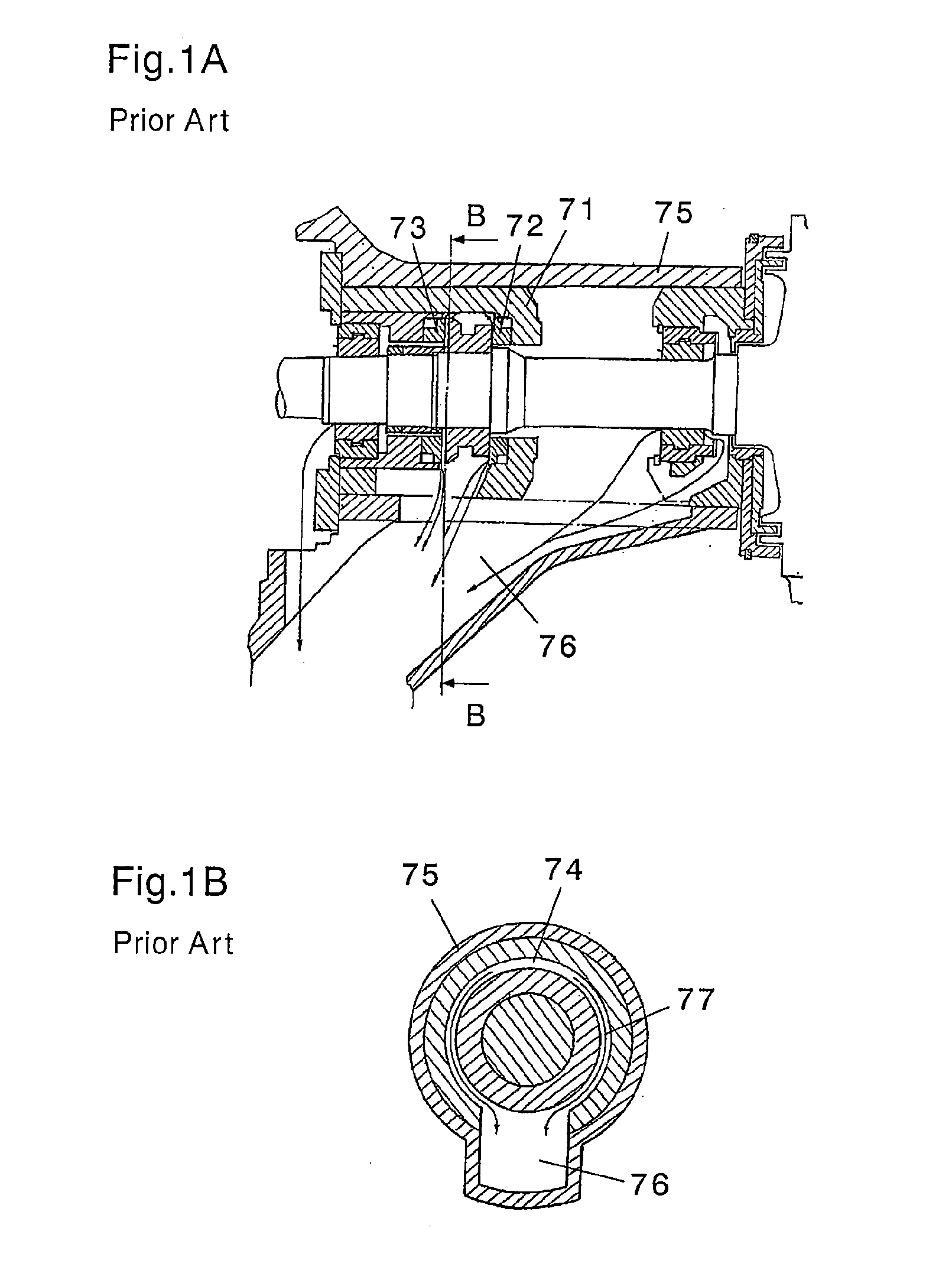
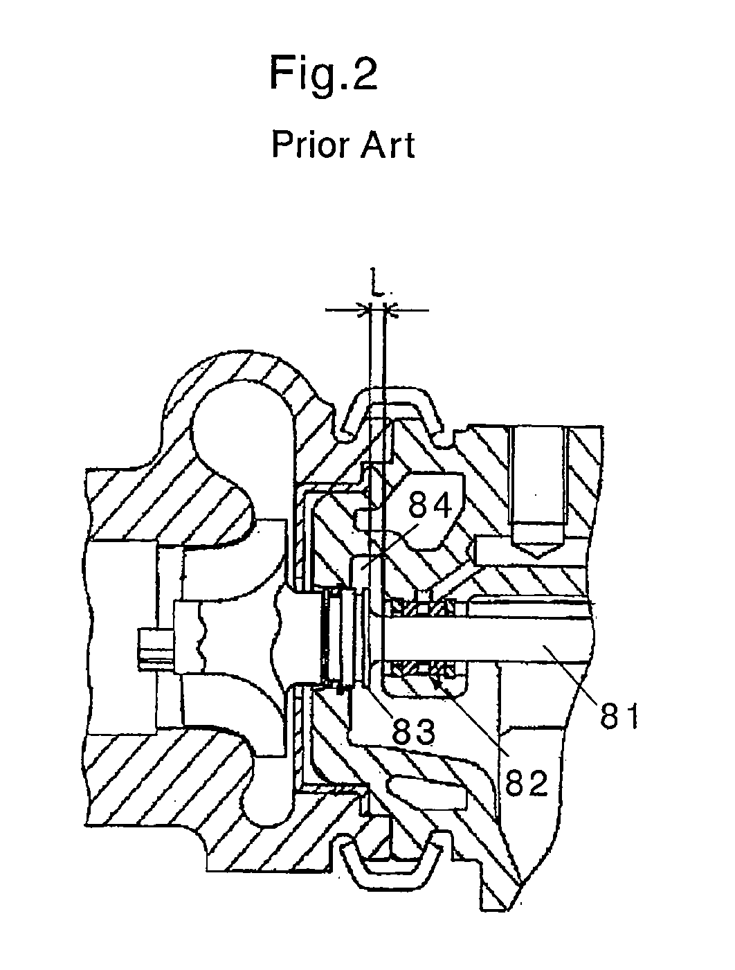
However, in the case that the thrust bearing is provided in a compressor side outer side of the radial bearing, the fed lubricating oil is hard to be discharged from the bearin

Method used


Image

  • Supercharger
  • Supercharger
  • Supercharger

Examples


Embodiment Construction

[0031]A description will be given below of a preferable embodiment in accordance with the present invention with reference to the accompanying drawings. In this case, in each of the drawings, the same reference numerals are attached to common portions, and an overlapping description will be omitted.

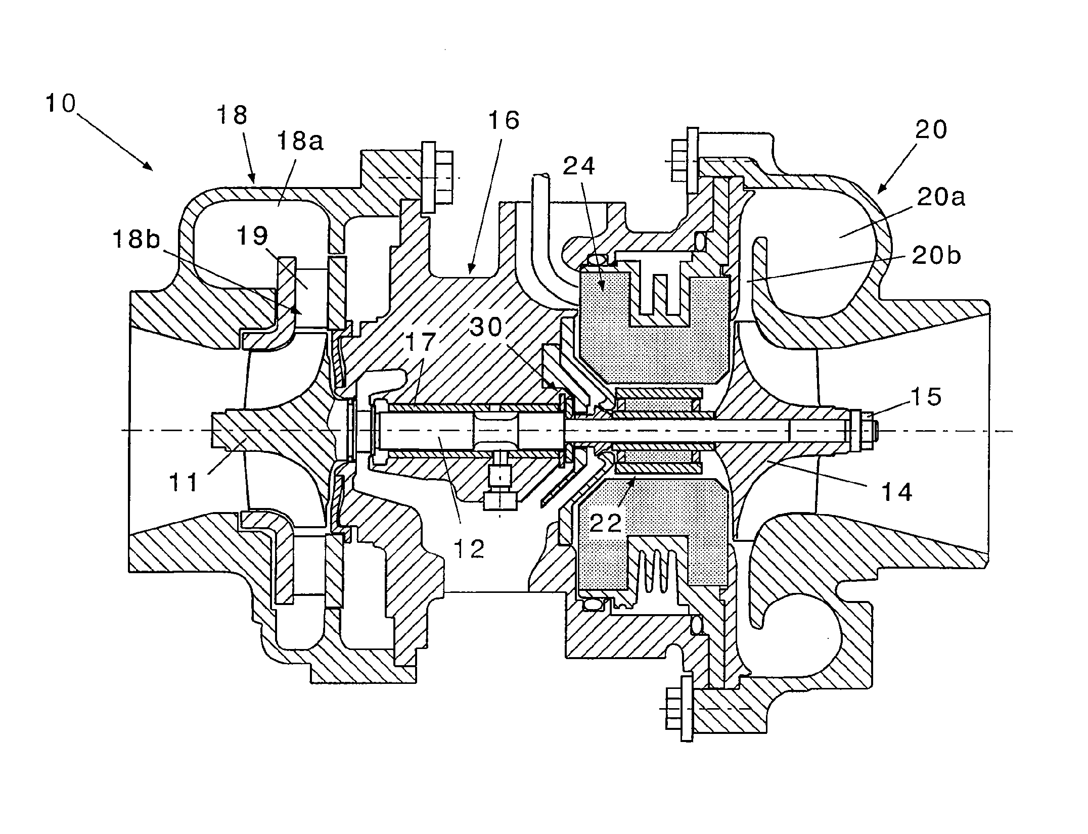
[0032]FIG. 3 is a schematic view of a whole structure of a supercharger in accordance with the present invention. In this drawing, a supercharger 10 in accordance with the present invention is provided with a turbine shaft 12, a compressor impeller 14, and a housing. The housing is constituted by a bearing housing 16, a turbine housing 18 and a compressor housing 20, in this embodiment.

[0033]The turbine shaft 12 has a turbine impeller 11 in one end (a left end in the drawing). In this embodiment, the turbine impeller 11 is formed integrally in the turbine shaft 12, however, the present invention is not limited to this, but may be structured such that the turbine impeller 11 is independent...


PUM


Abstract

Object The invention provides a supercharger which is provided with a thrust bearing in an outer side of a radial bearing, and can smoothly discharge a fed lubricating oil from a bearing portion so as to reduce a resistance generated by the lubricating oil.
Means to Solve the Problems The supercharger is provided with a thrust bearing (30) rotatably supporting a thrust force applied to a turbine shaft (12). The thrust bearing (30) is constituted by a disc-shaped thrust collar (32) rotating together with the turbine shaft, and a turbine side thrust bearing (34) and a compressor side thrust bearing (36) inhibiting a movement in an axial direction of the thrust collar. The compressor side thrust bearing (36) has an oil feed flow path (36a) feeding a lubricating oil to a surface coming into contact with a thrust collar from an inner side of a housing, an annular concave groove (36b) provided in an inner surface of a hollow through hole through which the turbine shaft passes, and an oil discharge flow path (36c) dropping down the lubricating oil reserved within the concave groove downward.

Description

BACKGROUND OF THE INVENTION[0001]The present invention relates to a supercharger.[0002]To feed an air having a density increased by a compressor to an engine is called as supercharging, and a structure providing for a driving work of the compressor by an exhaust gas is called particularly as an exhaust-gas turbocharger.[0003]The exhaust-gas turbocharger is constituted by a compressor and a turbine which are arranged while holding a bearing unit therebetween. The compressor has a compressor impeller built-in, and the turbine has a turbine impeller built-in, respectively. The compressor impeller and the turbine impeller are coupled to each other by a coupling shaft supported by the bearing unit, and are structured such that the turbine impeller is rotationally driven by an exhaust gas of the engine, a rotating force is transmitted to the compressor impeller via the coupling shaft, and the air is compressed by the compressor impeller so as to be supercharged to the engine.[0004]Patent ...

Claims


Application Information

Patent Timeline
IPC IPC(8): F04D29/04
CPCF01D25/168F01D25/18F02B37/10F05D2220/40F02B39/14Y02T10/144F02B39/10F16C17/04F16C33/1045F16C2360/24Y02T10/12
Inventor EGUCHI, MASATOSHIONITSUKA, KAZUHIROSHIMIZU, MASAHIRO
Owner IHI CORP
Why Eureka
Try Eureka