Vibration apparatus with rear motion inducer and frictionless coupling and methods for compensating load and controlling waveforms
What is Al technical title?
Al technical title is built by PatSnap Al team. It summarizes the technical point description of the patent document.
a rear motion inducer and vibration apparatus technology, applied in the field of vibration devices, can solve the problems of limited efficacy and/or range of use, user is subject to a relatively rough ride, and limit the range of use and ease of us
Inactive Publication Date: 2010-12-09
HEWITSON ANDREW MARK
View PDF13 Cites 10 Cited by
Summary
Abstract
Description
Claims
Application Information
AI Technical Summary
This helps you quickly interpret patents by identifying the three key elements:
Problems solved by technology
Method used
Benefits of technology
[0015]The present invention provides apparatus, systems and methods for a vibration apparatus with a moving platform, having (a) a platform sized and dimensioned for a person to stand, sit or lie upon; (b) a first motion inducer positioned other than under the platform; and a linkage that transfers a force from the first motion inducer to the platform, such that at least a first portion of the platfor...
Problems solved by technology
As a result of the vibration inducing mechanisms of McLeod, Trandafir, Kim, and Krompasick being disposed within the base and underneath the platform, the bases of such devices have a relatively great thickness, (e.g. 25.4 cm (10 inches) or more), which limits the range of use and ease of use due to the height of the platform from the ground (e.g., wheelchair access, seniors).
Such devices, however, are uneconomical, and limited in efficacy and/or range of use due to their small size.
As a result the user is subjected to a relatively rough ride that is uncomfortable and places undesirable shock loads on the joints of the user.
Another significant problem with the known vibration platforms is that they do not adequately compensate for the weight of the user.
While thi...
Method used
Image
Click on the blue label to locate the original text in one second.
Reading with bidirectional positioning of images and text.
Examples
Embodiment Construction
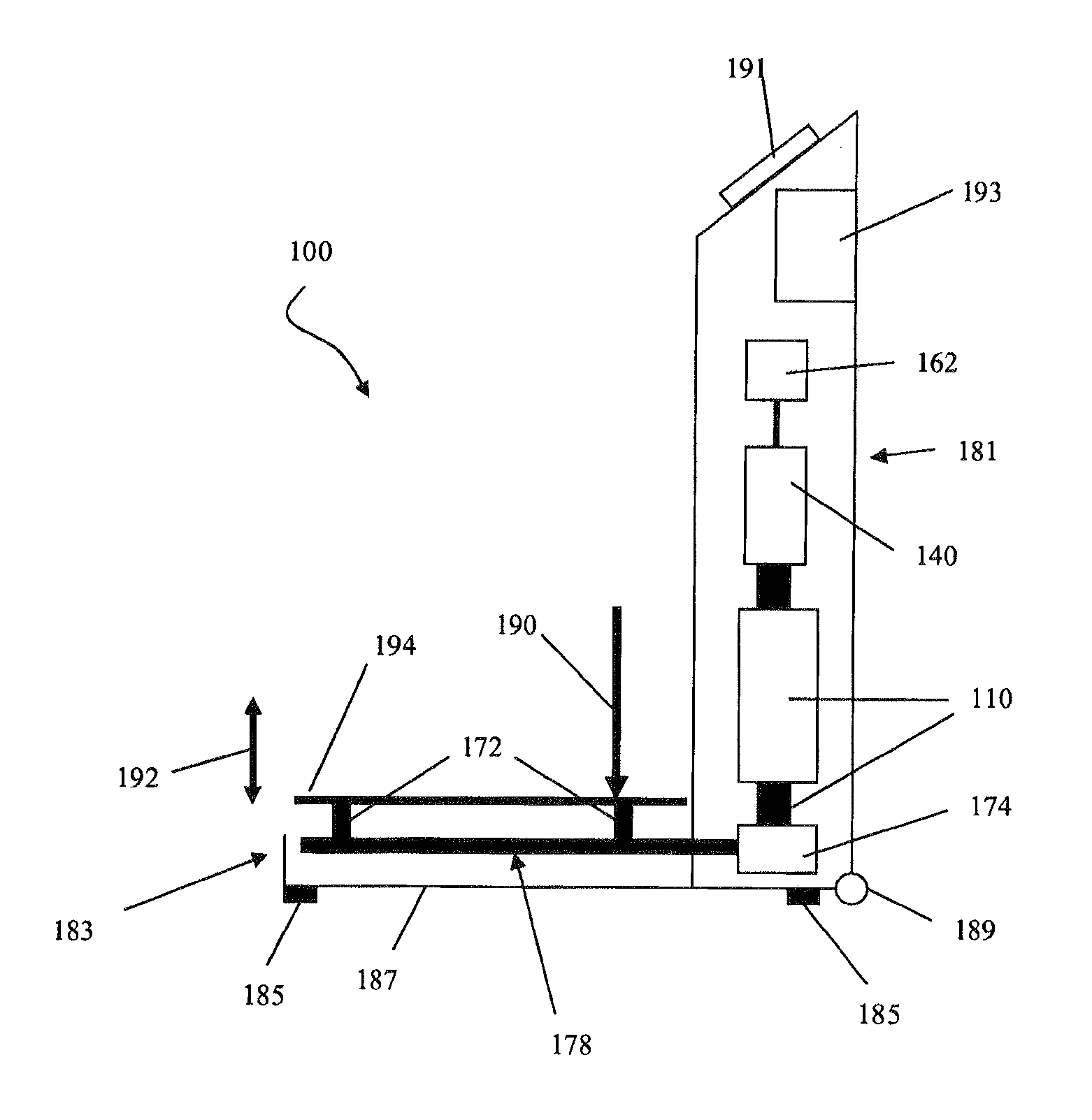
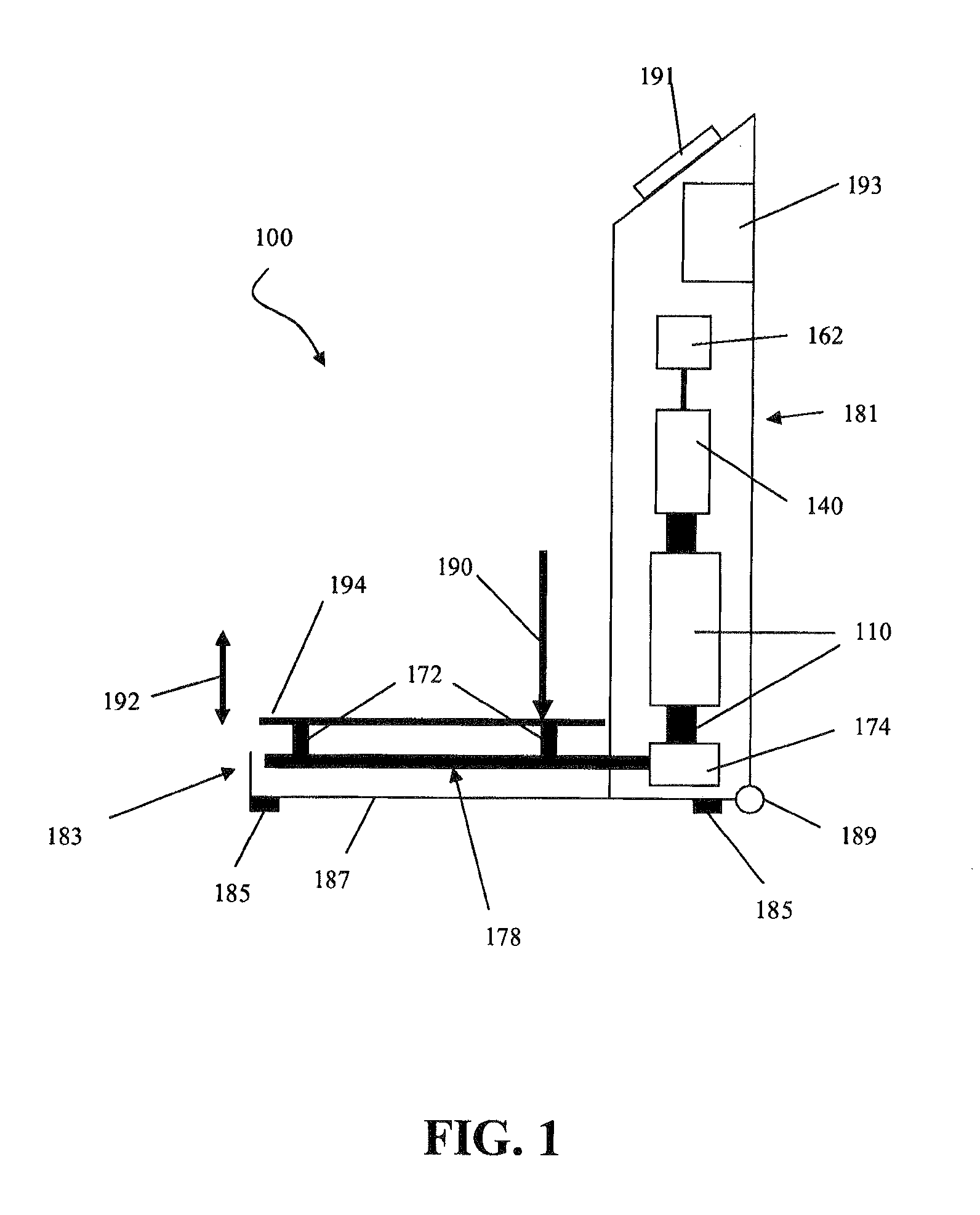
[0020]FIG. 1 is a cross sectional view of the vibration device 100 which generally includes two housings constituted by a tower 181 and a base 183. Preferably, vibration device 100 can be constructed out of a combination of metals, metal alloys, high impact plastics, and any reasonable combination thereof, in order to realize low residual vibration and minimal metal fatigue.
[0021]Base 183 is depicted generally as having a base frame 187, support feet 185, at least one of which is height adjustable, dolly wheels 189 to facilitate movement of the device, and vibrating platform 194.
[0022]Preferred vibrating platform 194 can be sized and dimensioned for a person to stand on, such that vibrating platform 194 has an upper surface area measuring at least 1 m2. In an alternate embodiment for exercise such as Pilates and Yoga platform 194 can have an upper surface area measuring at least 2 m2. Platform 194 preferably has a square or rectangular shape, but other suitable shapes are contemplat...
PUM
Abstract
A whole body vibration apparatus 100 with the motion inducing device 110 positioned other than under the vibrating platform 194 so that the vibrating platform 194 may be located close to the ground. Dual rocker shafts 178 journalled to reciprocate in a rotationally reciprocating motion, convert the linear motion of the rear-positioned motion inducing device 110 to vertical motion of the vibrating platform 194. A coupling mechanism constituted by a linkage 172, 174, 178 connects the motion inducing device 110 to the vibrating platform 194. The linkage employs deformable couplings 172, 174 and frictionless bearings to reduce unwanted rattle and wear and to remove the need for maintenance. A compensating device 140 adjusts for the weight of the user so that the motion inducing device 110 has all its useful output employed to vibrate the platform 194 as opposed to supporting the user's weight. In addition to altering frequency and amplitude, a method for user selection of different waveforms is provided to achieve a variety of treatment benefits.
Description
FIELD OF THE INVENTION[0001]The field of the invention is vibration devices for physiologically stimulating a living organism.BACKGROUND[0002]It has long been recognized that vibrational therapy and / or exercise is beneficial to the human body. For example, numerous publications and patents disclose various methods and / or vibration devices for exercise, speed and endurance training, promoting bone growth, therapeutically treating bone fractures, osteoporosis, other tissue conditions, postural instability, and other conditions such as cystic fibrosis, Parkinson's disease, arthritis, and multiple sclerosis.[0003]Typically, such vibrational devices include a base frame with a rigid platform configured to support a user, and a vibration inducing mechanism coupled to the platform, such as those disclosed in U.S. Pat. No. 5,376,065 to McLeod (December 1994), U.S. Pat. No. 6,234,975 to McLeod (May 2001), U.S. Pat. No. 6,843,776 to Trandafir (January 2005), U.S. Pat. App. Pub. No. 2006021764...
Claims
Application Information
Patent Timeline
Application Date:The date an application was filed.
Publication Date:The date a patent or application was officially published.
First Publication Date:The earliest publication date of a patent with the same application number.
Issue Date:Publication date of the patent grant document.
PCT Entry Date:The Entry date of PCT National Phase.
Estimated Expiry Date:The statutory expiry date of a patent right according to the Patent Law, and it is the longest term of protection that the patent right can achieve without the termination of the patent right due to other reasons(Term extension factor has been taken into account ).
Invalid Date:Actual expiry date is based on effective date or publication date of legal transaction data of invalid patent.
IPC IPC(8): A61H1/00
CPCA61H1/005A61H23/0218A61H2201/5064A61H2203/0406
Inventor BECKER, CARL MARTHINUSHEWITSON, ANDREW MARK