High efficiency r744 refrigeration system and cycle

a refrigeration system and high efficiency technology, applied in the field of refrigeration units and operation cycles, can solve the problems of unfavorable operation efficiency, uncertainty about toxicity and flammability, and large amount of energy, and achieve the effects of reducing the total compression of the refrigeration cycle, reducing the electric power consumption of the vapor compressor, and improving cycle efficiency

Inactive Publication Date: 2010-12-16
R & D DYNAMICS
View PDF7 Cites 48 Cited by
  • Summary
  • Abstract
  • Description
  • Claims
  • Application Information

AI Technical Summary

Benefits of technology

[0016]In accordance with an advantage of the present invention, two independent ejectors are utilized to reduce total compression of the refrigeration cycle, and, as a result, reduce the electric power consumption of the vapor compressor. As a further result, the refrigeration system operates with higher cycle efficiency than for prior art systems.
[0017]In accordance with another advantage of the present invention, the system can be operated with negligible global warming potential and zero ozone depletion potential.
[0018]In accordance with yet another advantage of the present invention, the system is not limited to being used with any one refrigerant, which means that any refrigerants, including the preferred R744 refrigerant, may be used without departing from the spirit and principles of the invention.
[0019]In another aspect of the present invention a refrigeration cycling method comprises providing a mechanical vapor compressor having a low-pressure side and a high-pressure side, a first ejector in operative communication with the high-pressure side of the vapor compressor, and a second ejector in operative communication with the low-pressure side of the vapor compressor. Pursuant to the method, vapor-phase refrigerant discharged from the vapor compressor is mixed with a pressurized sub-cooled liquid in the first ejector so as to boost the pressure of the vapor-phase refrigerant to an elevated pressure that is greater than the pressure of either the input vapor-phase refrigerant received from the vapor compressor or the pressurized sub-cooled liquid. The vapor stream discharged from the first ejector is converted into a sub-cooled liquid-phase refrigerant. Within the second ejector, the vapor-phase refrigerant is mixed with the sub-cooled liquid-phase refrigerant so as to boost the pressure of the vapor-phase refrigerant to an elevated pressure. The mixed refrigerant discharged from the second ejector is then separated into a vapor-phase and a liquid-phase, with the separated liquid-phase refrigerant being evaporated into a vapor-phase refrigerant that is provided to an input of the second ejector for mixing with the sub-cooled liquid-phase refrigerant therein, and the separated vapor-phase refrigerant being superheated and provided to the low-pressure side of the vapor compressor.
[0020]As one example of potential applications for the present invention, a 150-ton capacity, water-cooled chiller cycle is considered. The water-cooled chiller cycle is predicted through a preliminary cycle analysis for standard rating conditions controlled by ARI 550 / 590 to provide power consumption as low as 0.47 kW / ton, which corresponds to about 7.47 of Coefficient of Performance (COP).
[0021]The present invention cycle can be applied to air conditioning and refrigeration units and systems for various applications, including residential, automobile, industrial and commercial applications. The present invention is adaptable to various types of mechanical vapor compressors to accommodate various such applications. The liquid centrifugal pump of the disclosed embodiments can be either positive displacement machines or high-speed turbomachines. Heat exchanging methods used in the refrigeration cycle of the units or systems can be air-cooled, water-cooled or both.

Problems solved by technology

Emissions of halogenated synthetic refrigerants represent a major challenge for the environment due to their green house warming potential, as well as their contribution to ozone depletion.
However, there is still uncertainty about toxicity and flammability, which are critical to human life and safety.
However, in a press release issued on Oct. 31, 2008, Toyota Germany decided to move away from HFO-1234yf for car air conditioners after several independent tests raised issues about its flammability.
However, in ordinary use, the low critical temperature of R744 (approximately 31° C.) forces the air conditioning system to work in the transcritical cycle at significantly higher pressures than desired.
Accordingly, such prior art systems using R744 tend to utilize increased amounts of energy and thus, have not operated efficiently.
For example, even though the increased performance density of R744 leads to smaller and lighter components, the basic transcritical cycle is potentially less efficient than a conventional vapor compression cycle because it suffers from larger thermodynamic losses at such a low critical temperature.
Higher heat rejection temperatures with increased loss of energy result in greater throttling losses.
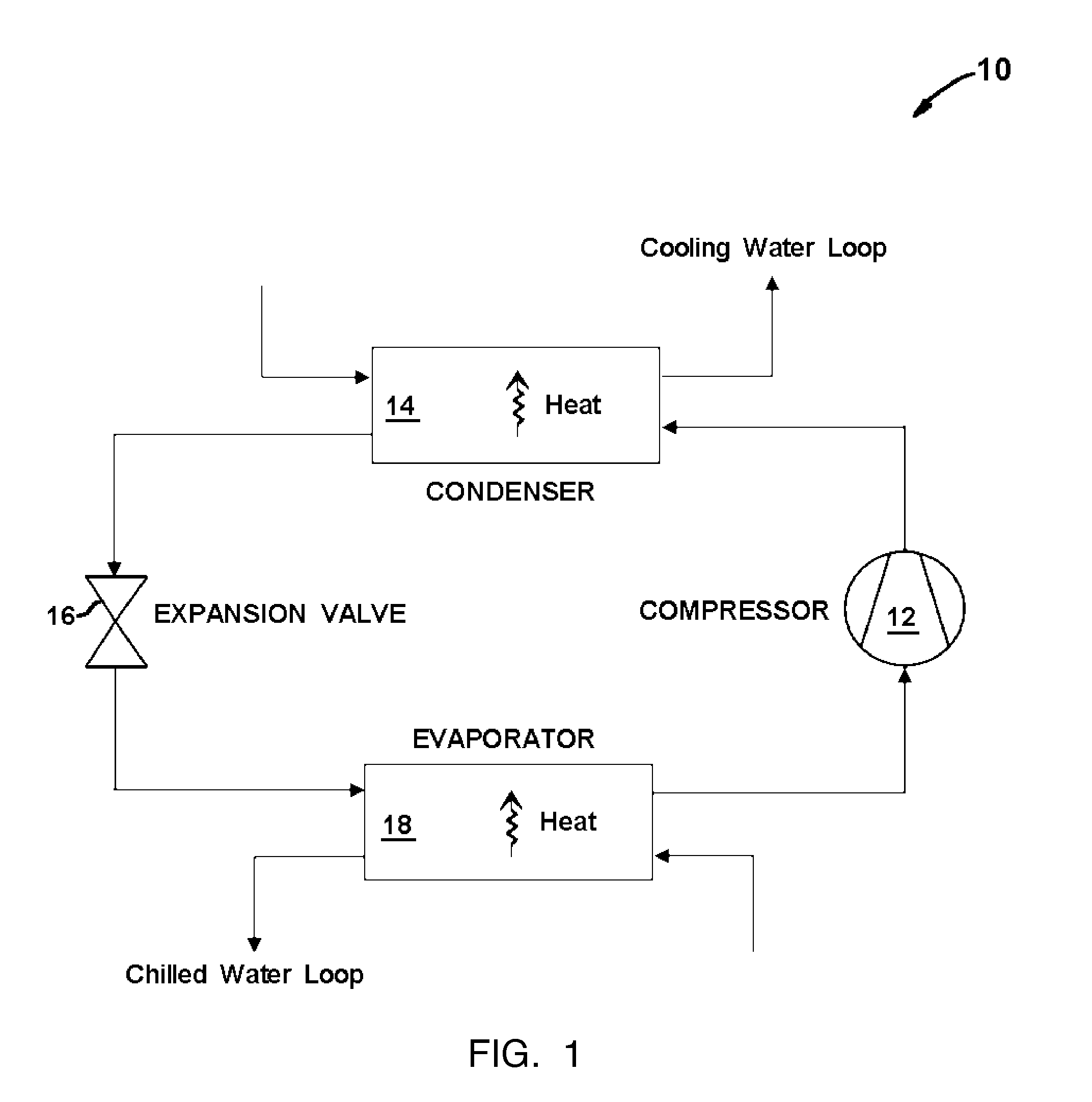
A direct application of R744 to the conventional air conditioning and refrigeration cycle therefore requires high power consumption, which is not desirable.
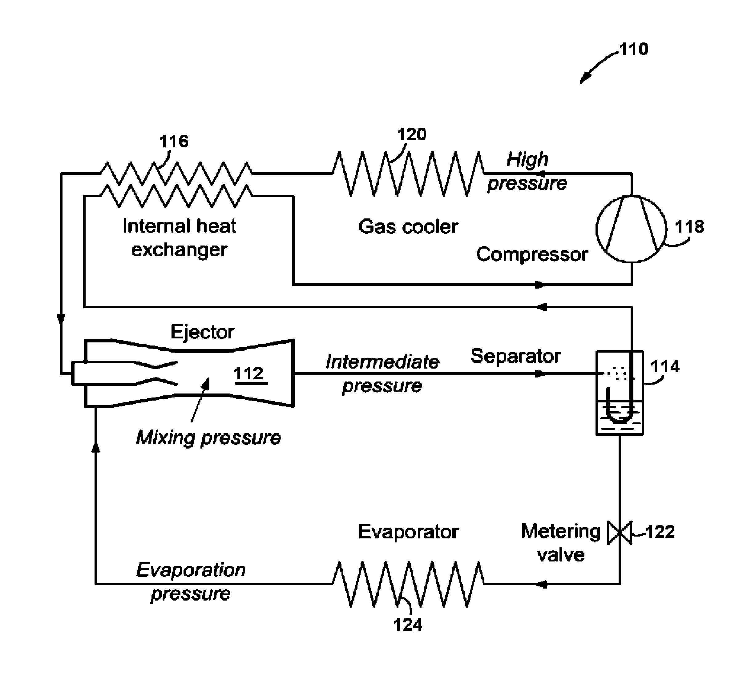
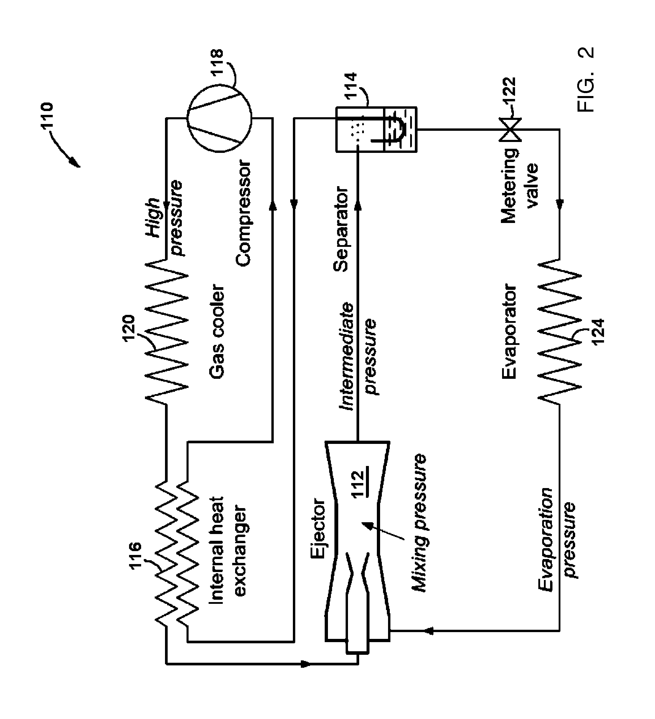
Thus, the refrigeration cycle 110 requires high power consumption, which is not desirable or efficient.

Method used


Image

  • High efficiency r744 refrigeration system and cycle
  • High efficiency r744 refrigeration system and cycle
  • High efficiency r744 refrigeration system and cycle

Examples


Embodiment Construction

[0027]FIGS. 3 and 4 represent an R744 vapor compression refrigeration system and cycle in accordance with the present invention. More specifically, FIG. 3 illustrates the present invention in the form of a water-cooled chiller, generally designated by reference numeral 210, which is one of several applications for the innovative refrigeration cycle of the present invention. FIG. 4 provides an exemplary pressure-enthalpy thermodynamic diagram for the water-cooled chiller of FIG. 3. Both FIGS. 3 and 4 identify and correspond to various steps in the refrigeration cycle by reference to encircled reference numerals.

[0028]The illustrated water-cooled chiller generally has a 150-ton capacity and comprises a mechanical vapor compressor 212 driven by a high-speed electric motor 214. The vapor compressor 212 may be either a single stage or multi-staged compressor and of either a positive displacement-type or a centrifugal turbo-type. As illustrated in FIG. 3, the compressor 212 is a centrifug...


PUM


Abstract

A high efficiency R744 air conditioning and refrigeration system and cycle comprises a vapor compressor and two independent ejectors operatively connected to high and low-pressure sides of the compressor, respectively. The two ejectors reduce the overall pressure ratio of the mechanical vapor compressor resulting in dramatically increased thermodynamic cycle efficiency. As one example of its potential applications for residential, commercial or industrial uses, a 150 ton capacity of a water-cooled chiller designed in accordance with the present invention is predicted to provide the power consumption as low as 0.47 kW/ton, when operated in accordance with the cooling methods of the present invention, which corresponds to 7.47 of Coefficient of Performance (COP).

Description

CROSS-REFERENCE TO RELATED APPLICATION[0001]This application claims the benefit of U.S. Provisional Application No. 61 / 185,834, filed Jun. 10, 2009, which is incorporated herein by reference.TECHNICAL FIELD OF THE INVENTION[0002]The present invention relates to refrigeration units and operation cycles, and more particularly to an R744 (carbon dioxide) vapor compression refrigeration system usable in numerous applications with improved cycle efficiency without any detrimental environmental effect.BACKGROUND OF THE INVENTION[0003]From residential or automobile air conditioning units to large packaged water chillers for air conditioning and refrigeration in commercial and industrial facilities, all mechanical vapor compression cycles now generally use environmentally harmful chemical refrigerants of hydrochlorofluorocarbon (HCFC) or hydrofluorocarbon (HFC) fluids. Emissions of halogenated synthetic refrigerants represent a major challenge for the environment due to their green house wa...

Claims


Application Information

Patent Timeline
Patent Type & Authority Applications(United States)
IPC IPC(8): F25B1/00F25B1/06F25B43/00F25B1/10
CPCF25B9/008F25B40/00F25B41/00F25B2309/061F25B2341/0012F25B2341/0015
Inventor OH, JONGSIKAGRAWAL, GIRIDHARI L.BUCKLEY, CHARLES WILLIAM
Owner R & D DYNAMICS
Why Eureka
Try Eureka