Phase variable device in car engine

Inactive Publication Date: 2010-12-16
NITTAN VALVE CO LTD
View PDF1 Cites 7 Cited by
  • Summary
  • Abstract
  • Description
  • Claims
  • Application Information

AI Technical Summary

Benefits of technology

[0034]When a torque is imparted from the camshaft ((30)) to the intermediate rotational body ((33)), the local frictional force that takes place between the second rotational body ((35)) and the intermediate rotational body ((33)) can be enhanced by reducing the eccentric distance between the center of the second circular eccentric cam ((36)) and the rotational axis of the second rotational body ((35)), and by enhancing the force exerted by the intermediate rotational body ((33)) onto the second rotational body ((35)). On the other hand, the travel distance of the cam guide plate relative to the intermediate rotational body 33 is increased by increasing the distance between the first circular eccentric cam ((36)) and the rotational axis of the second rotational body ((35)). That is, both the frictional force between the second rotational body ((35)) and the intermediate rotational body ((33)) and the relative travel distance of the cam guide plate ((37)) are simultaneously increased by changing the eccentric distance from the rotational axis L1 of the second rotational body to the first and second eccentric cams.
[0035]In the invention defined in claim 1, if a torque is transmitted from the camshaft ((30)) in operation to the intermediate rotational body ((33)) which causes a delay in phase angle of the camshaft relative to the first rotational body, self-lock effect is evoked in response to the torque to stop the relative rotation of

Problems solved by technology

Such unintended change in the coupling angle in turn causes problematic errors in intake valve timing/exhaust valve timing.
However, in the event that the speed of the colliding spherical bodies 16 i

Method used


Image

  • Phase variable device in car engine
  • Phase variable device in car engine
  • Phase variable device in car engine

Examples


second embodiment

[0039]FIGS. 1 through 18 show a first and the phase variable device in accordance with the present invention.

first embodiment

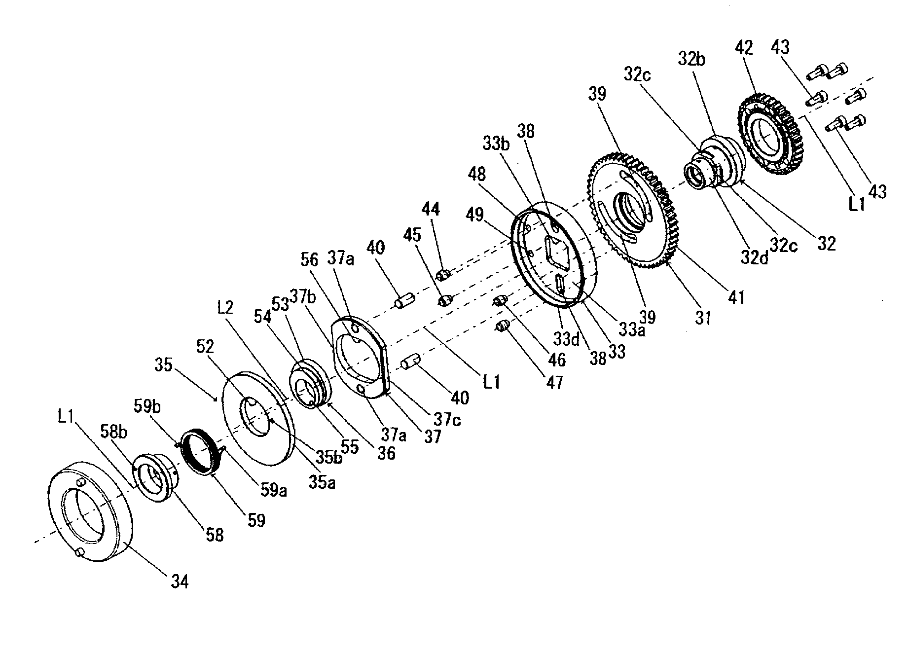
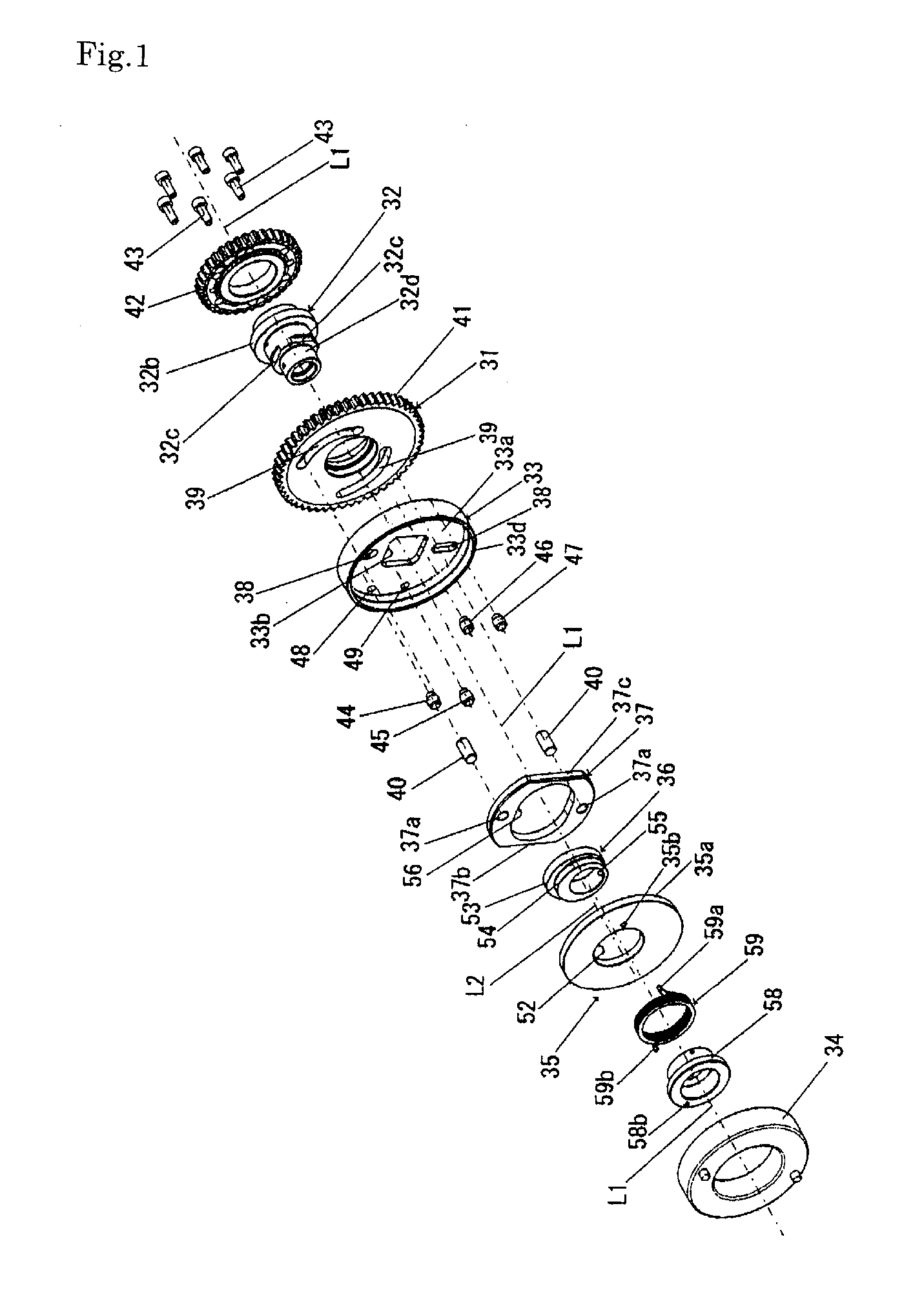
[0040]FIG. 1 is an exploded perspective view of a phase variable device for use with a car engine in accordance with the invention.

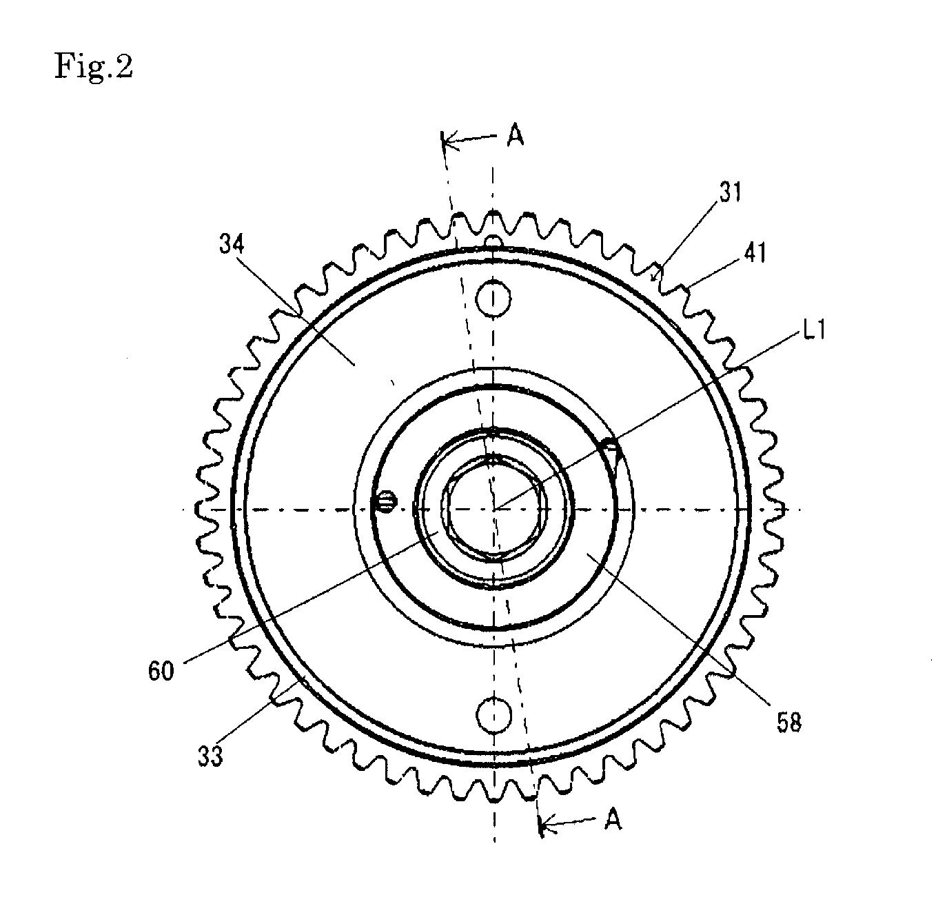
[0041]FIG. 2 is a front view of the first phase variable device of FIG. 1.

[0042]FIG. 3 shows an axial cross section of the first phase variable device taken along line A-A of FIG. 2.

[0043]FIG. 4 shows a vertical cross section of a second rotational body and a rotational guide plate (or intermediate rotational body) taken along line B-B of FIG. 3. FIG. 6 shows a vertical cross section of a first rotational body taken along line D-D of FIG. 3.

[0044]FIG. 7 is a diagram illustrating a relationship between the second rotational body and a circular eccentric cam.

[0045]FIG. 8 illustrates the circular eccentric cam in operative contact with the cam guide plate.

[0046]FIG. 9 illustrates the first rotational body in operative contact with guide pins (or slide members).

[0047]FIGS. 10(a) through (c) show different specifications of the circular eccentric cam in oscil...


PUM


Abstract

The invention provides a phase variable device for use with a car engine, capable of preventing the phase angle of the camshaft from varying relative to the first circular rotational body even if the camshaft is subjected to the reaction of a valve spring, and capable of reducing the impulsive generated in the phase variable device and delivered to the engine. MEANS FOR ACHIEVING THE OBJECT
The objects can be achieved by the inventive phase variable device which includes: a first rotational body, an intermediate rotational bode integral with the camshaft of an engine, a second rotational body, all rotatably arranged on the same camshaft, the device adapted to control phase angle of the second rotational body, thereby varying the phase angle of the intermediate rotational body. The second rotational body is placed in substantial contact with the inside of the hollow cylindrical section of the intermediate rotational body. A circular eccentric cam, integral with the second rotational body and adapted to rotate about an eccentric center thereof, causes a cam guide plate to reciprocate in the direction perpendicular to the rotational axis, which in turn causes slide members protruding from the cam guide plate to move in the radial guides formed in one of the first rotational body and the intermediate rotational body, as well as in skewed guides which are formed in the other one and skewed with respect to a circumference coaxial with the skewed guides.

Description

TECHNICAL FIELD[0001]This invention relates to a phase variable device for controlling opening / closing timing of a valve of a car engine by applying a torque to a rotatable drum so as to change the rotational phase angle of the camshaft relative to the sprocket of the engine.BACKGROUND ART[0002]A conventional valve timing control device of this type is disclosed in Patent Document 1 below. This valve timing device has: a drive plate 3 rotatablly mounted on a camshaft 1 subjected to the driving force transmitted thereto from the engine crankshaft 1; a driven shaft member 9 directly mounted on the camshaft 1 and having a conversion guide 11 which is mounted on the circumference of the camshaft 1 and spaced apart from the front face of the drive plate 3; and an intermediate rotational body 5 which is rotatably mounted forwardly of the conversion guide 11 on the driven shaft member 9 via a shaft bearing 14.[0003]The drive plate 3 has radial guides 10, while the driven shaft member 9 has...

Claims


Application Information

Patent Timeline
IPC IPC(8): F01L1/34
CPCF01L1/344F01L1/352F01L1/356F01L2001/3522F01L2820/031
Inventor KAMEDA, MICHIHIRONAGADOH, MASAYASU
Owner NITTAN VALVE CO LTD
Why Eureka
Try Eureka