

Authentication with built-in encryption by using moire parallax effects between fixed correlated s-random layers
- Summary
- Abstract
- Description
- Claims
- Application Information
AI Technical Summary
Benefits of technology
Problems solved by technology
Method used
Image

Examples
example 1
2D Random Parallax Moire with Linear Transformations
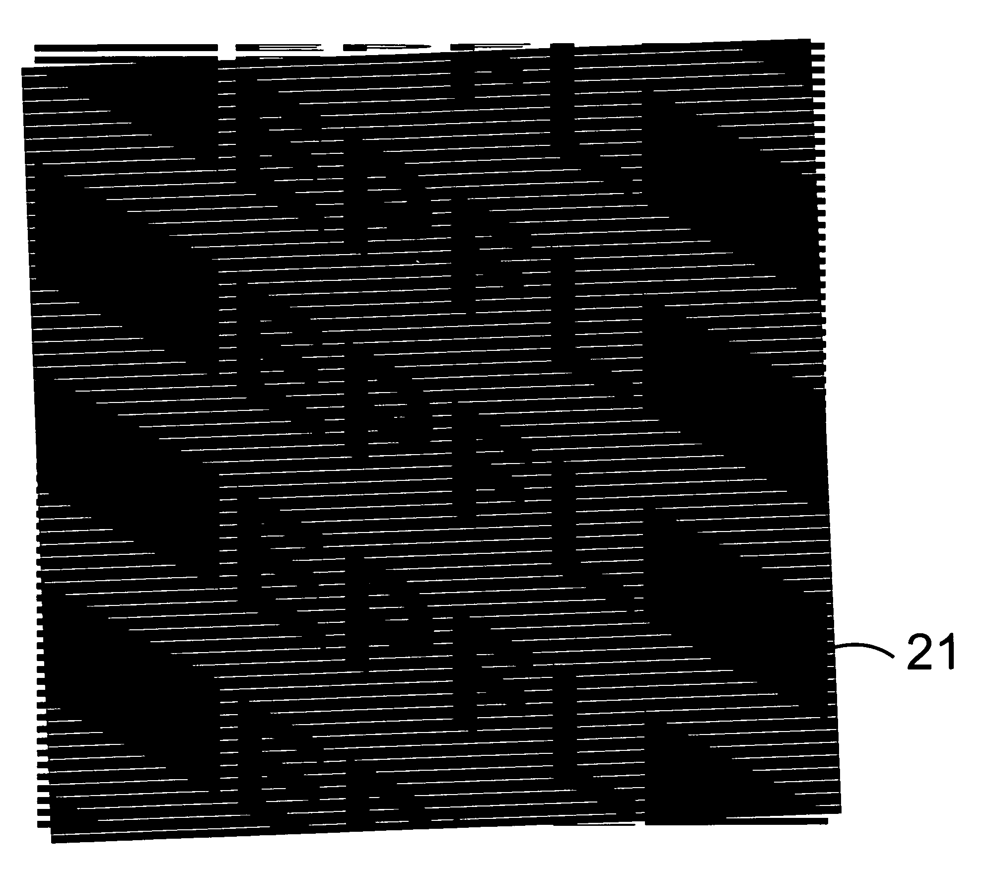
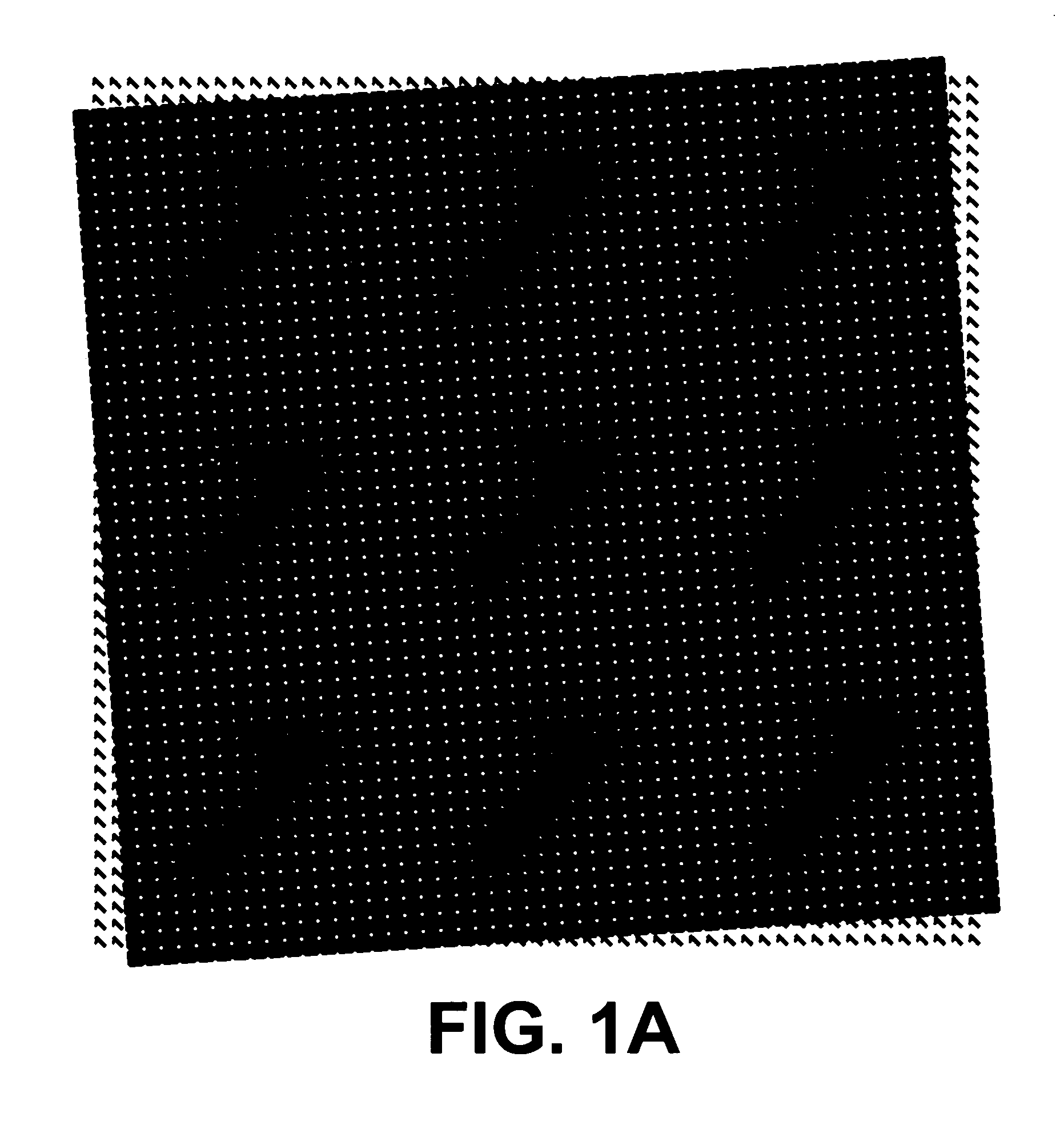
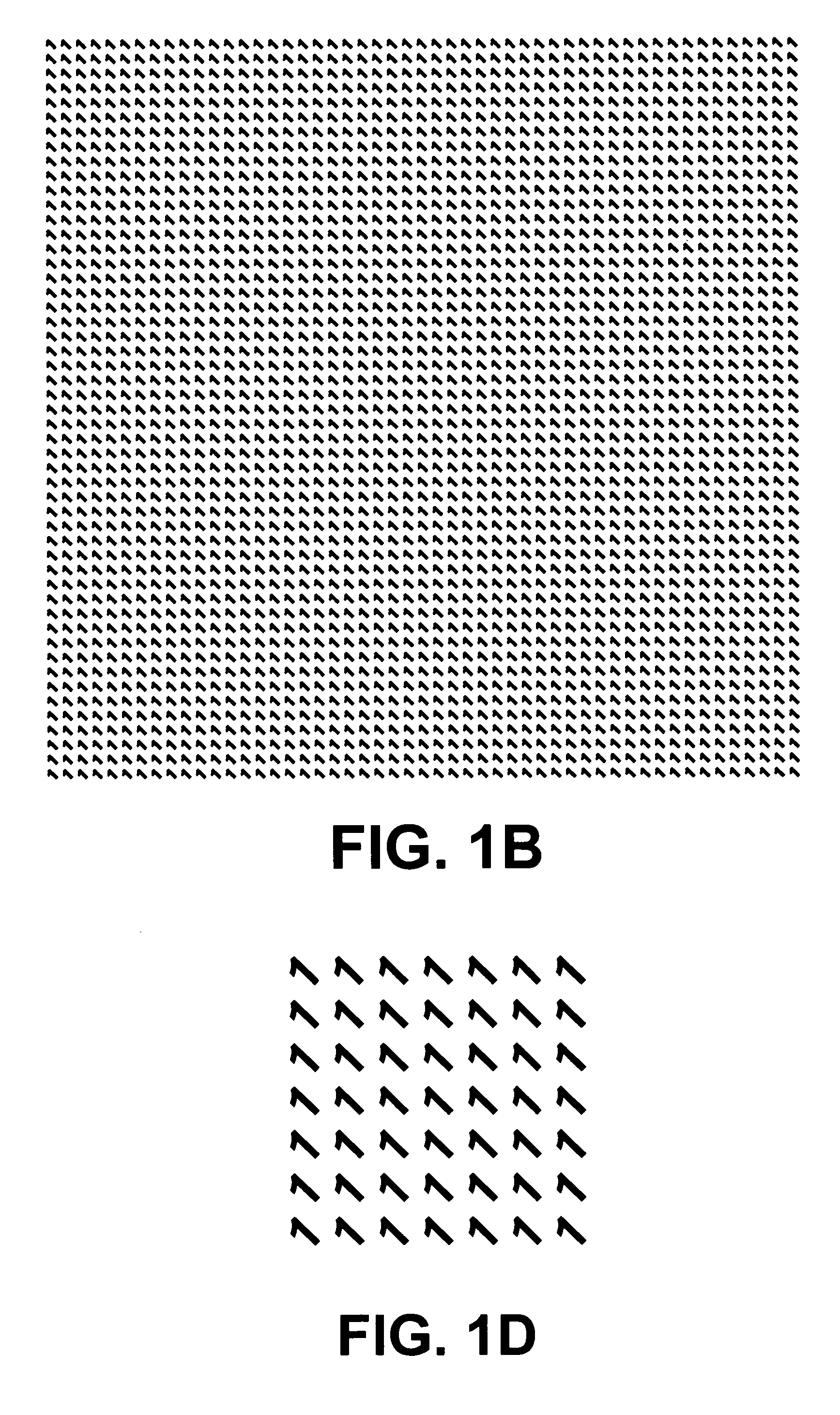
[0119]In this example, the base layer consists of randomly located “1”-shaped dots, as shown in FIG. 3B, and the revealing layer consists of tiny pinholes (or microlens lenslets) that are located in the same random locations as in the base layer (see FIG. 3C). Obviously, if the two layers are superposed on top of each other precisely dot on dot no moire effect will be generated in the superposition (in fact, this is a singular moire situation in which the moire effect is infinitely big and therefore invisible). But if we apply to the revealing layer a small rotation (which is a linear transformation) before it is fixed on the base layer, a “1”-shaped moire effect will become visible as shown in FIG. 3A.
[0120]Now, thanks to the “basic rule of the parallax moire effect” (see above), the dynamic evolution of a parallax moire effect when tilting the compound layer (or moving the eyes) horizontally (or respectively, vertically) is the s...
example 2
Another 2D Random Parallax Moire with Linear Transformations
[0121]If, instead of applying a rotation to one of the two layers as in the previous example we apply a scaling transformation, the resulting dynamic parallax moire effect is not an “orthoparallax” effect but rather an “intuitive” parallax effect, namely, when the compound layer is tilted horizontally the parallax moire effect moves horizontally (as in FIG. 8), and when the compound layer is tilted vertically the parallax moire effect moves vertically (as in FIG. 9).
example 3
2D Random Parallax Moire with Non-Linear Transformations
[0122]This example shows a strongly non-linear case, in which a horizontal tilt of the compound layer gives a circular rotation of the moire (as shown in FIG. 14), while a vertical tilt gives a radial motion of the moire (as shown in FIG. 13).
[0123]In order to obtain this moire effect we start with two original random dot screens having identical dot locations, one of which consists of dots having the shape of tiny “1”s, as shown in FIG. 3B, while the other consists of tiny pinholes on a black background (or an equivalent microlens array) as shown in FIG. 3C. In order to obtain the desired moire effect, we may define the moire transformation gM(x,y) using the well known log-polar transformation as follows:
gM(xy)=(ɛlog(x2+y2)ɛarctan(y / x))(1)
where ε is a small positive constant. Note that by using here the logarithm of the radius rather than the radius itself we obtain gradually increasing elements along the radial direction, whi...
PUM
 Abstract
Description
Claims
Application Information