
Method and apparatus for surface contour mapping

Active Publication Date: 2010-12-16
APPLE INC
View PDF6 Cites 43 Cited by
  • Summary
  • Abstract
  • Description
  • Claims
  • Application Information

AI Technical Summary

Benefits of technology

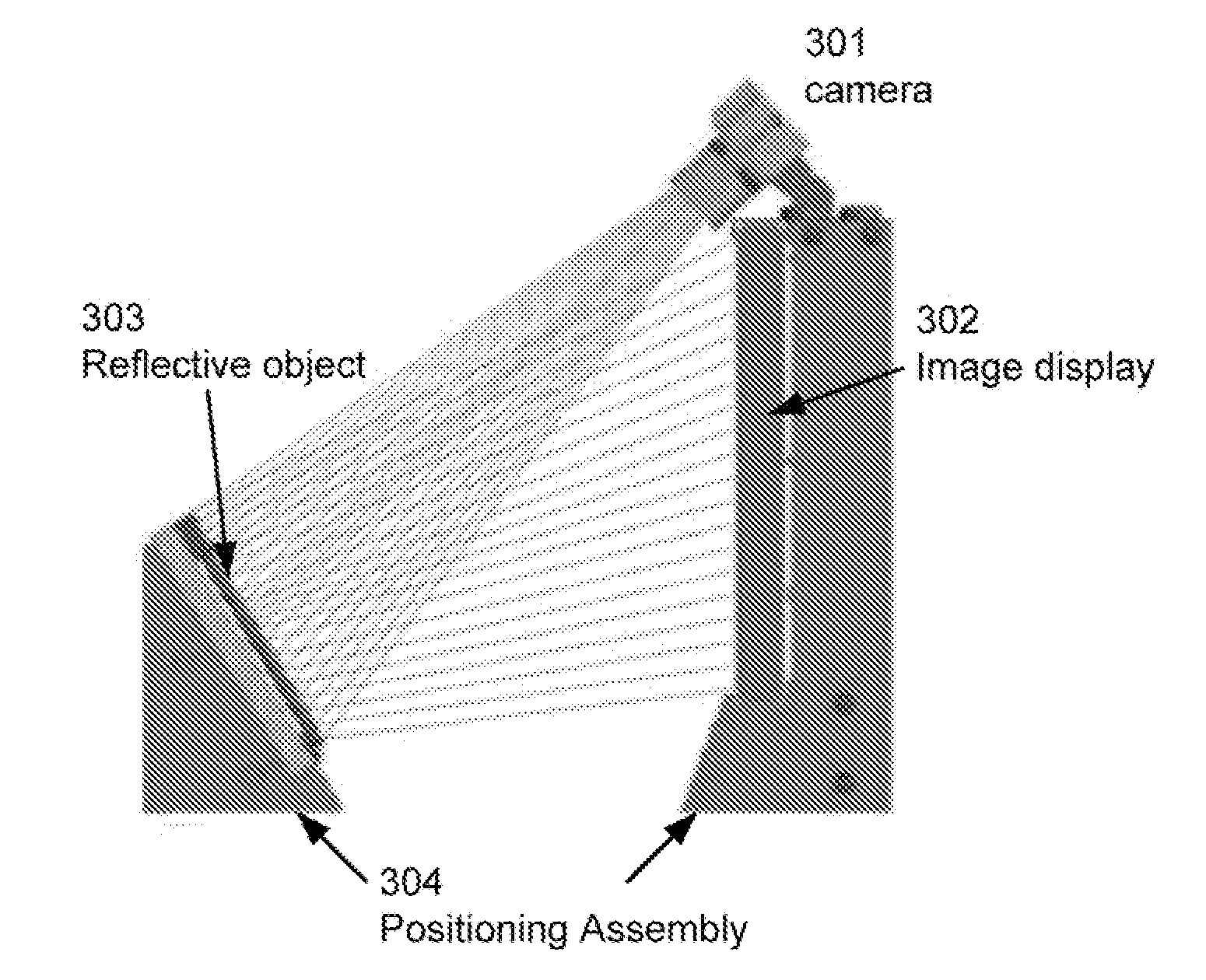
[0005]In another embodiment, a method for estimating a three-dimensional surface shape of an object having a specular reflective surface is disclosed. The method includes at least the following operations: calibrating a position and direction of an image capture device relative to a support member of a positioning assembly, projecting by a light transmitting device an image pattern on the specular reflective surface positioned on the support member of the positioning assembly, capturing by the image capture device an image reflection of the transmitted image pattern reflected by the specular reflective surface, determining adjacency information between a plurality of two-dimensional points in the captured image reflection, estimating a three-dimensional point of the surface of the reflective object that corresponds to a two-dimensional point in the captured image reflection by minimizing a curvature function of a path that connects the first three-dimensional point to a previously estimated three-dimensional point of the surface that corresponds to an adjacent two-dimensional point in the captured image reflection, and displaying the estimated three-dimensional surface shape of the reflective object.

Problems solved by technology

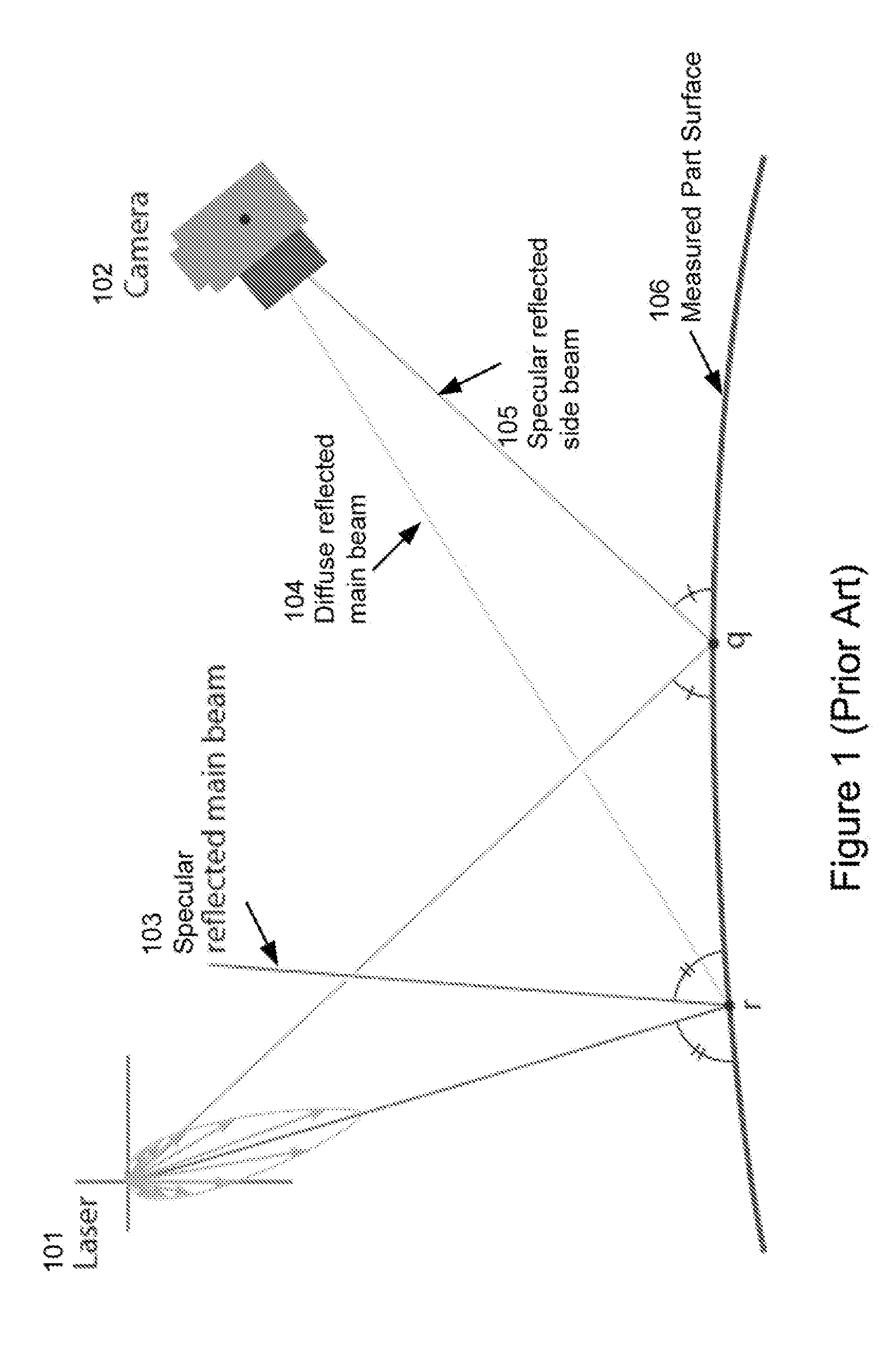
While accurate, the mechanical profilometer can be slow and therefore inappropriate in a high volume manufacturing or a rapid prototyping environment that requires quick results.
In addition contact measurement can be undesirable because of potential damage to the surface of the manufactured part.
While again such systems can provide accurate results, the measurement process can be slow, and the specialized measurement equipment can be costly.

Method used


Image

  • Method and apparatus for surface contour mapping
  • Method and apparatus for surface contour mapping
  • Method and apparatus for surface contour mapping

Examples


Embodiment Construction

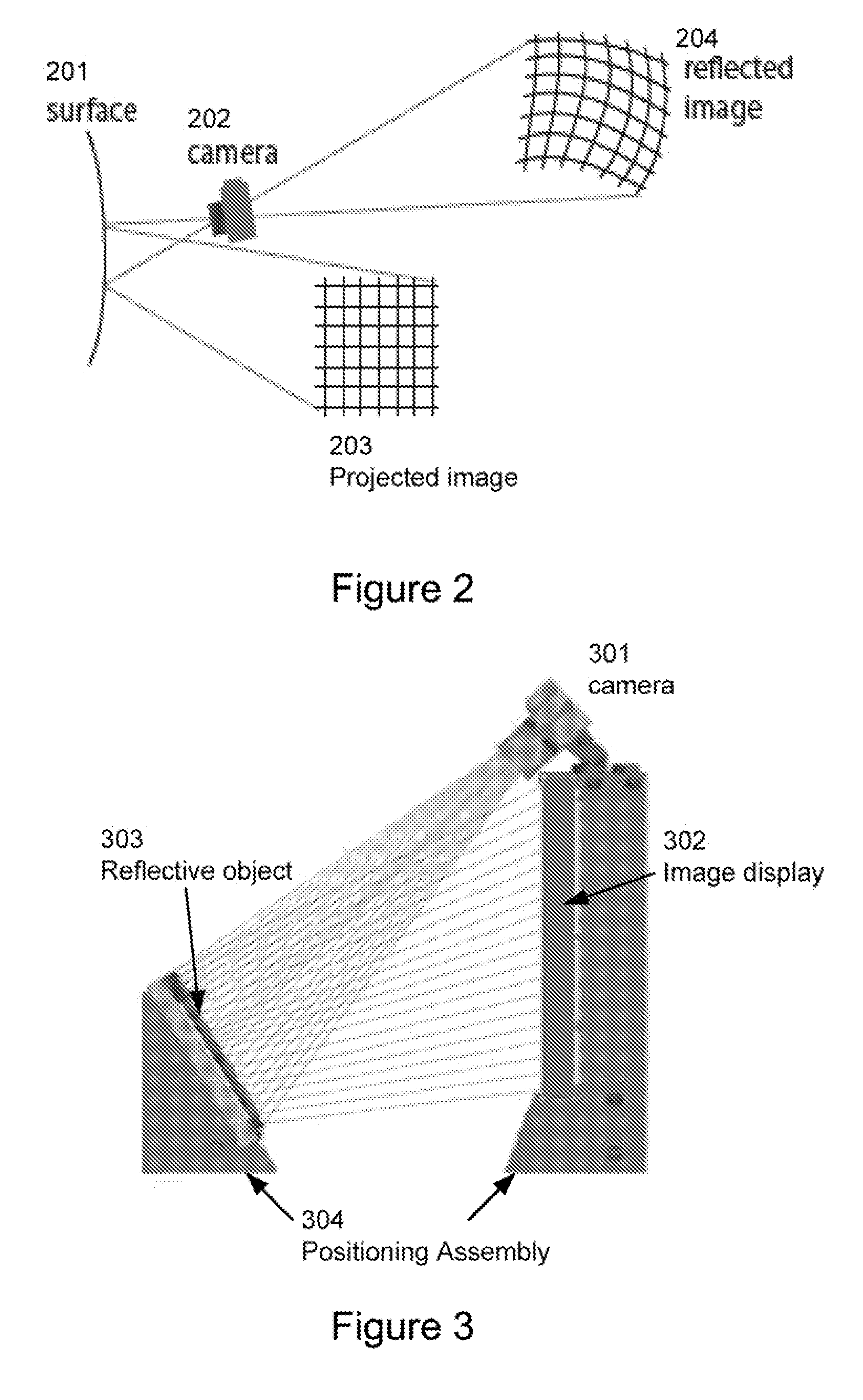
[0004]A method for estimating a three-dimensional surface shape of an object having a specular reflective surface is disclosed. The method can be carried out by at least projecting a image pattern on the specular reflective surface, capturing a reflected image pattern from the specular reflective surface by an image capture device, comparing a set of two-dimensional reflected image points in the reflected image pattern to the projected image pattern to generate an estimate of the three-dimensional surface shape of the reflective object, and displaying the estimate of the three-dimensional surface shape of the reflective object.

[0005]In another embodiment, a method for estimating a three-dimensional surface shape of an object having a specular reflective surface is disclosed. The method includes at least the following operations: calibrating a position and direction of an image capture device relative to a support member of a positioning assembly, projecting by a light transmitting d...


PUM


Abstract

The three dimensional surface shape of a specular reflective object can be determined by examining a captured image reflected from the object. Flat specular reflective surfaces, e.g. a mirror, provide an undistorted reflected image, while curved surfaces reflect a distorted image altered by the surface shape. By analyzing one or more captured images of the distorted reflection, one can estimate the shape of the surface that caused the distortion. A captured distorted image can be compared to a reference undistorted image for which one knows some geometric properties. A system to capture and process such images can be assembled from a few components including a computer to generate and process the images, a display to project the image onto the reflective object, a digital camera to capture the reflected image and a positioning device on which to orient the components with respect to each other.

Description

CROSS-REFERENCE TO RELATED APPLICATIONS[0001]This patent application claims the benefit of priority under 35 U.S.C. 119(e) to U.S. Provisional Patent Application Ser. No. 61 / 187,562 filed on Jun. 16, 2009 entitled “REFLECTIONS ON SHAPE” by Andre et al. which is hereby incorporated by reference herein for all purposes.TECHNICAL FIELD[0002]The present invention relates generally to the estimation of a three dimensional surface shape of an object. More particularly, methods, software, hardware, and systems are described for rapidly determining the surface profile of an object from a photographic image of a reflected light pattern from the object.BACKGROUND OF THE INVENTION[0003]Accurately measuring the three dimensional shape of a manufactured part, such as a casing or enclosure, can be accomplished using a mechanical profilometer, which measures a vertical displacement of a stylus in contact with the manufactured part for different horizontal movements. While accurate, the mechanical ...

Claims


Application Information

Patent Timeline
IPC IPC(8): G06T15/00
CPCG01B11/2513G06T7/521
Inventor ANDRE, BARTLEY K.CANNON, SCOTTKESSLER, PATRICK
Owner APPLE INC
Learn More