A/D converter, solid-state image capturing apparatus and electronic information device

a solid-state image and converter technology, applied in the direction of radio frequency controlled devices, instruments, television systems, etc., to achieve the effect of reducing power consumption, reducing the layout area of the a/d converter, and fast ra

Active Publication Date: 2010-12-16
SHARP KK
View PDF4 Cites 26 Cited by
  • Summary
  • Abstract
  • Description
  • Claims
  • Application Information

AI Technical Summary

Benefits of technology

[0082]In the present invention, when the second switch is turned on, the voltage level of a terminal, applied with the analog input signal, of the second sampling capacitance element is a voltage value very close to the transitionally stabilized first voltage level of the analog input signal, the voltage level of the terminal being stabilized after electric charge distribution. Thus, when the second switch is turned on, the voltage level of a terminal, applied with the analog input signal, of the second sampling capacitance element is set to near the first voltage level and is subsequently settled. That is, stabilization is made to the first voltage level at a fast rate. Therefore, even if a period for the sample hold circuit to sample the second voltage level of the analog input signal is short, the second voltage level can be precisely sampled. The second voltage level mentioned herein is defined to be a voltage level equal to or below the first voltage level.
[0083]In the present invention, a period for the third switch to be turned on is set to be variable and the on-period of the third switch is controlled so that when the second switch is turned on, the voltage of a terminal of the second sampling capacitance element, applied with the analog input signal, becomes a voltage value very close to the first voltage level, which is transitionally stabilized, and the voltage level of the terminal of the second sampling capacitance element is stabilized after electric charge distribution when the second switch is turned on. Thereby, optimization is possible to sample hold the second voltage level of the analog input signal in a shorter period of time.
[0084]In the present invent...

Problems solved by technology

This causes a problem of narrowing a voltage range which c...

Method used


Image

  • A/D converter, solid-state image capturing apparatus and electronic information device
  • A/D converter, solid-state image capturing apparatus and electronic information device
  • A/D converter, solid-state image capturing apparatus and electronic information device

Examples


embodiment 1

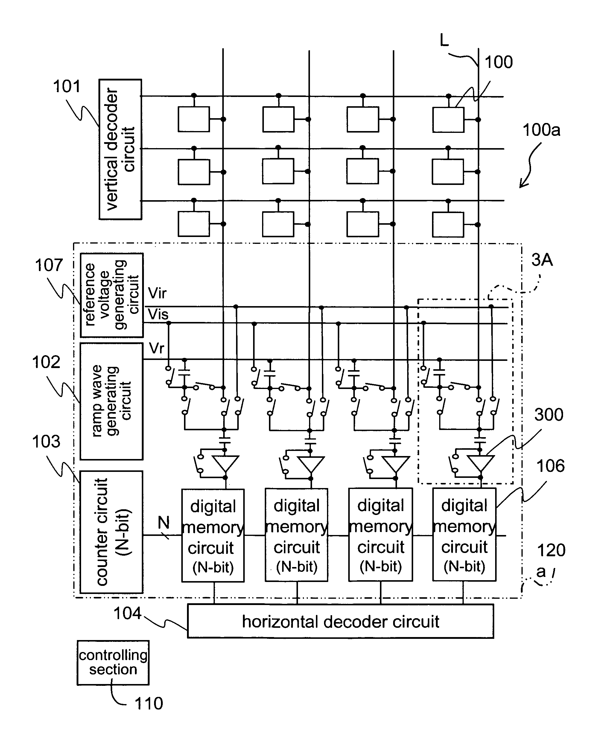
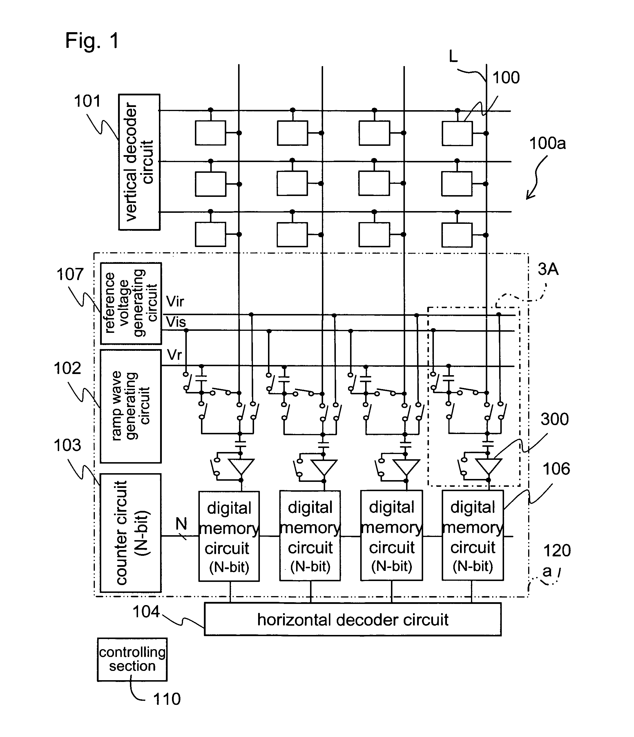
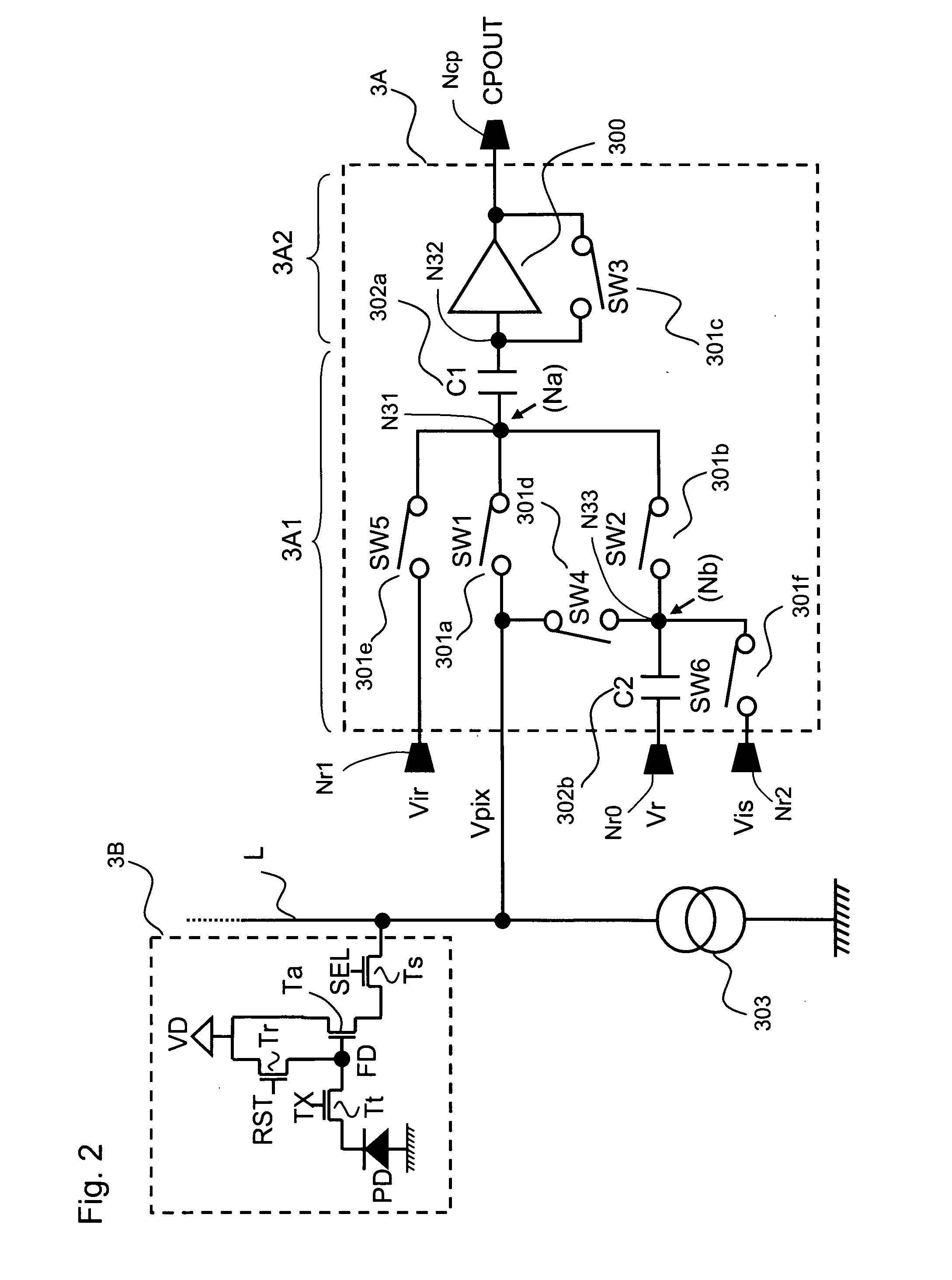
[0127]FIG. 1 is a diagram describing a system configuration of a CMOS image sensor including an A / D converter according to Embodiment 1 of the present invention. FIG. 2 is a diagram illustrating a sample hold circuit and comparing circuit section in the A / D converter according to Embodiment 1 of the present invention, together with a configuration of a pixel.

[0128]Note that, in Embodiment 1 and other embodiments described thereafter, unless a particular description is necessary, switches, comparing circuits and digital memory circuits will be turned into models to be illustrated in figures. Further, it is needless to say that the embodiments of the present invention will be limited to exemplary configurations of the CMOS image sensor illustrated hereinafter.

[0129]A CMOS image sensor 100a according to Embodiment 1 includes: a plurality of pixels 100 arranged in rows and columns; a vertical decoder circuit 101 for selecting a pixel row of the plurality of pixels 100 arranged in rows a...

embodiment 2

[0181]FIG. 7 is a diagram describing a solid-state image capturing apparatus according to Embodiment 2 of the present invention, illustrating specific elements of a sample hold circuit and comparing circuit section constituting an A / D converter in the solid-state image capturing apparatus. FIG. 8 is a diagram describing an A / D converter in the solid-state image capturing apparatus according to Embodiment 2 of the present invention, illustrating a sample hold circuit and comparing circuit section in the A / D converter together with a configuration of a pixel.

[0182]In the A / D converter according to Embodiment 2, and further in a sample hold circuit and comparing circuit section (SHC circuit section) 12A therein, a sample hold circuit 12A1 includes: two capacitance elements 1202a and 1202b (hereinafter, each one of them will be referred to as C1 and C2); and five switches 1201a, 1201b, 1201d, 1201e and 1201f (hereinafter, the respective switches will be referred to as SW1, SW2, SW4, SW5...

embodiment 3

[0206]FIG. 10 is a block diagram schematically illustrating an exemplary configuration of an electronic information device as Embodiment 3 of the present invention, including the solid-state image capturing apparatus according to Embodiment 1 or 2 used in an image capturing section thereof.

[0207]The electronic information device 90 according to Embodiment 3 of the present invention as illustrated in FIG. 10 includes either of the solid-state image capturing apparatuses according to Embodiments 1 and 2 of the present invention as an image capturing section 91 for capturing a subject. The electronic information device 90 further includes at least any of: a memory section 92 (e.g., recording media) for data-recording a high-quality image data obtained by being captured by an image capturing section, after predetermined signal processing is performed on the image data for recording; a display section 93 (e.g., liquid crystal display device) for displaying this image data on a display sc...


PUM


Abstract

The CMOS image sensor according to the present invention includes a sample hold section 3A1 for retaining an analog input signal voltage and a ramp wave signal voltage; and a comparing section 3A2 for taking an output from the sample hold section 3A1 as an input to compare it with a reverse level of itself, in which the sample hold section 3A1 applies a stabilization promoting voltage to a terminal of the sampling capacitance element so that an electric potential level of the terminal of the sampling capacitance element is promoted to become stabilized at a predetermined voltage, when the analog input signal is applied to the terminal of the sampling capacitance element.

Description

[0001]This nonprovisional application claims priority under 35 U.S.C. §119(a) to Patent Application No. 2009-142491 filed in Japan on Jun. 15, 2009, the entire contents of which are hereby incorporated by reference.BACKGROUND OF THE INVENTION[0002]1. Field of the Invention[0003]The present invention relates to an A / D converter, a solid-state image capturing apparatus, and an electronic information device, and more particularly, to an A / D converter for converting an analog signal to digital data, a solid-state image capturing apparatus including the A / D converter, and an electronic information device including the solid-state image capturing apparatus used therein. The present invention is on the basis of the underlying technology of column-parallel A / D converters, in which a sample hold section and a comparing section are arranged for each column, and which are used for CCD and CMOS image sensors, near-infrared and far infrared image sensors and the like, in which an element for con...

Claims


Application Information

Patent Timeline
IPC IPC(8): H04N5/335H03M1/12H01L27/146H03M1/56H04N5/357H04N5/363H04N5/369H04N5/374H04N5/3745H04N5/378
CPCH03M1/0607H03M1/123H03M1/1295H03M1/56H04N5/37457H04N5/378H04N25/778H04N25/75
Inventor HOSHINO, KOZO
Owner SHARP KK
Why Eureka
Try Eureka