Image display apparatus

a technology of image display and display screen, which is applied in the direction of printers, instruments, camera focusing arrangement, etc., can solve the problems of low light efficiency, short life, and long time requirements, and achieve the effect of reducing the influence of image quality deterioration and equal image quality

Inactive Publication Date: 2010-12-16
SHARP KK
View PDF6 Cites 69 Cited by
  • Summary
  • Abstract
  • Description
  • Claims
  • Application Information

AI Technical Summary

Benefits of technology

[0013]The present invention was conceived in view of the situations and it is therefore the object of the present invention to provide an image display apparatus capable of controlling a spot size on a screen in accordance with an image projection size or user's operation so as to reduce an influence of image quality deterioration due to the spot size on the screen generated when using a highly directional light source such as a laser beam and a scanning type image forming means.Means for Solving the Problems

Problems solved by technology

However, such a lamp has not only problems that a life time is short and that a long time is required for turning on but also requires an optical system for separating three primary colors of red, green, and blue from a light source, problems of low efficiency of use of light, complicated structure, and poor color reproducibility.
Since a size of the spatial modulation element must be expanded to a beam diameter and the light must be equalized in an element surface, such a projection type image display apparatus using a spatial modulation element needs mechanisms such as a fly-eye lens and an optical integrator and is difficult to be miniaturized.

Method used


Image

  • Image display apparatus
  • Image display apparatus
  • Image display apparatus

Examples


first embodiment

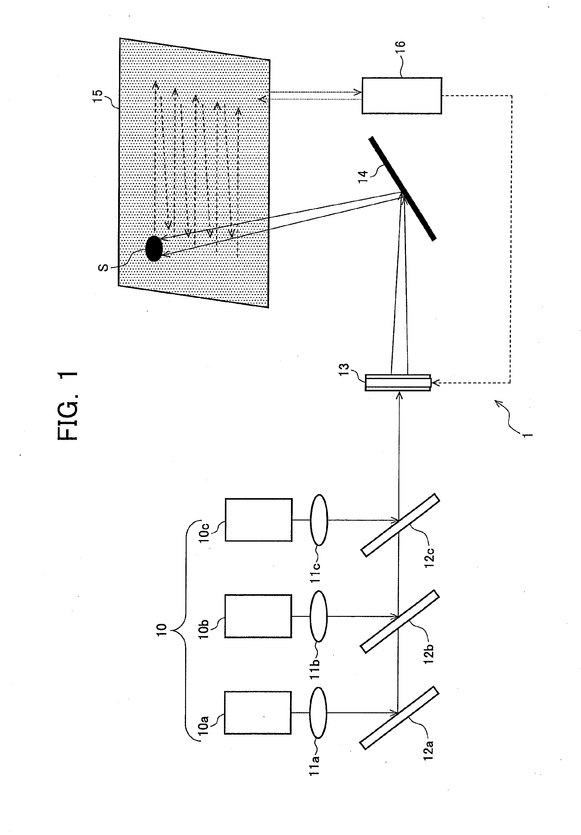
[0035]FIG. 1 is a diagram of an exemplary configuration of an image display apparatus according to a first embodiment of the present invention and, in FIG. 1, 1 denotes an image display apparatus.

[0036]The image display apparatus 1 depicted in FIG. 1 is made up of a laser light source device 10 made up of laser light sources 10a to 10c of R (red), G (green), and B (blue), collimating lenses 11a to 11c that collimate output light beams into parallel lights, dichroic mirrors 12a to 12c that only reflect wavelengths of their respective light beams, a variable focus device 13, a MEMS (Micro Electro Mechanical System) mirror 14 that forms an image with a scanning method, a screen 15 that displays an image, and a distance detecting device 16 that detects a distance to the screen 15. The variable focus device may be disposed on a light path of a light beam emitted from the laser light source device 10 and reaching the MEMS mirror 14.

[0037]For example, the laser light source device 10 may h...

second embodiment

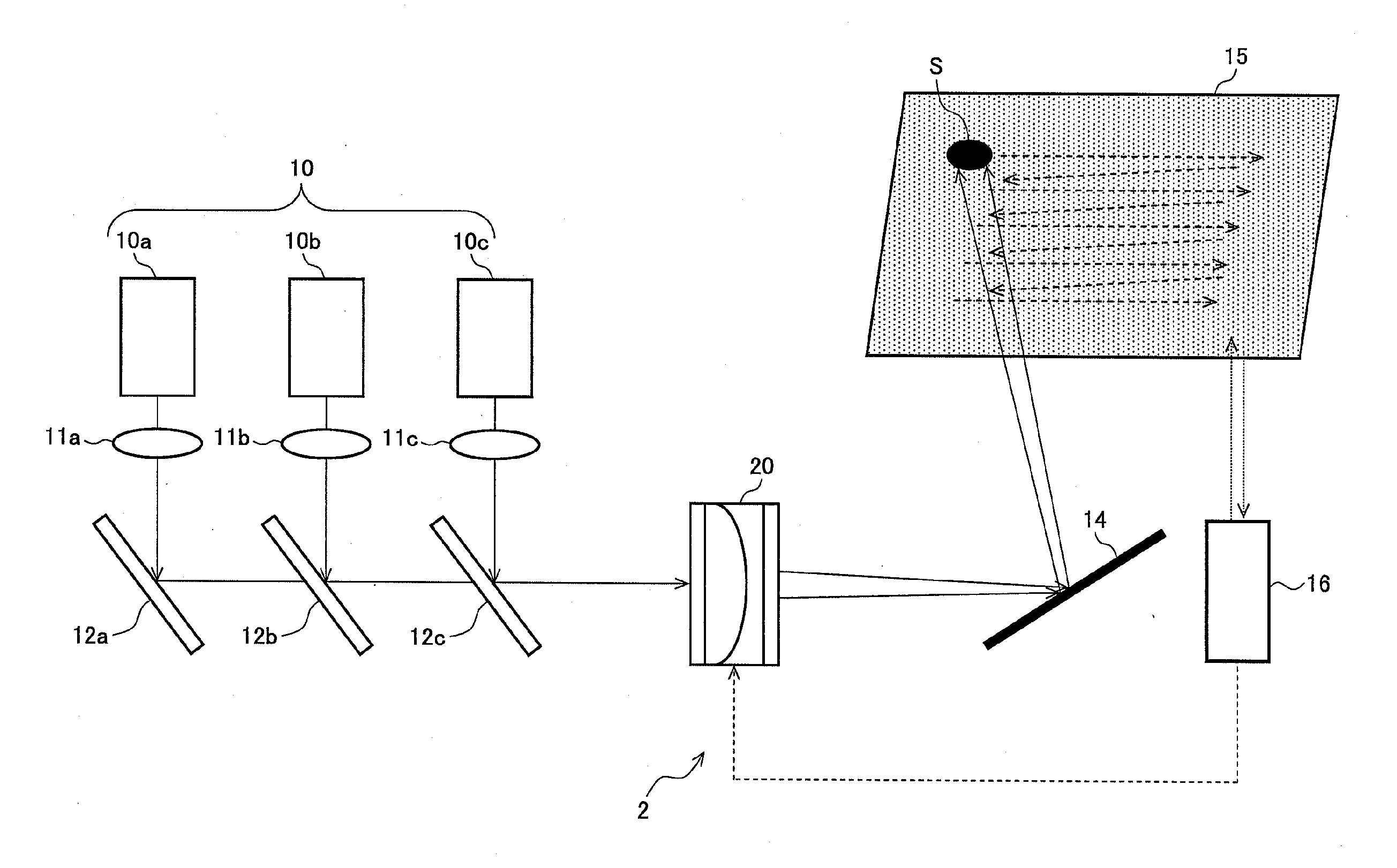
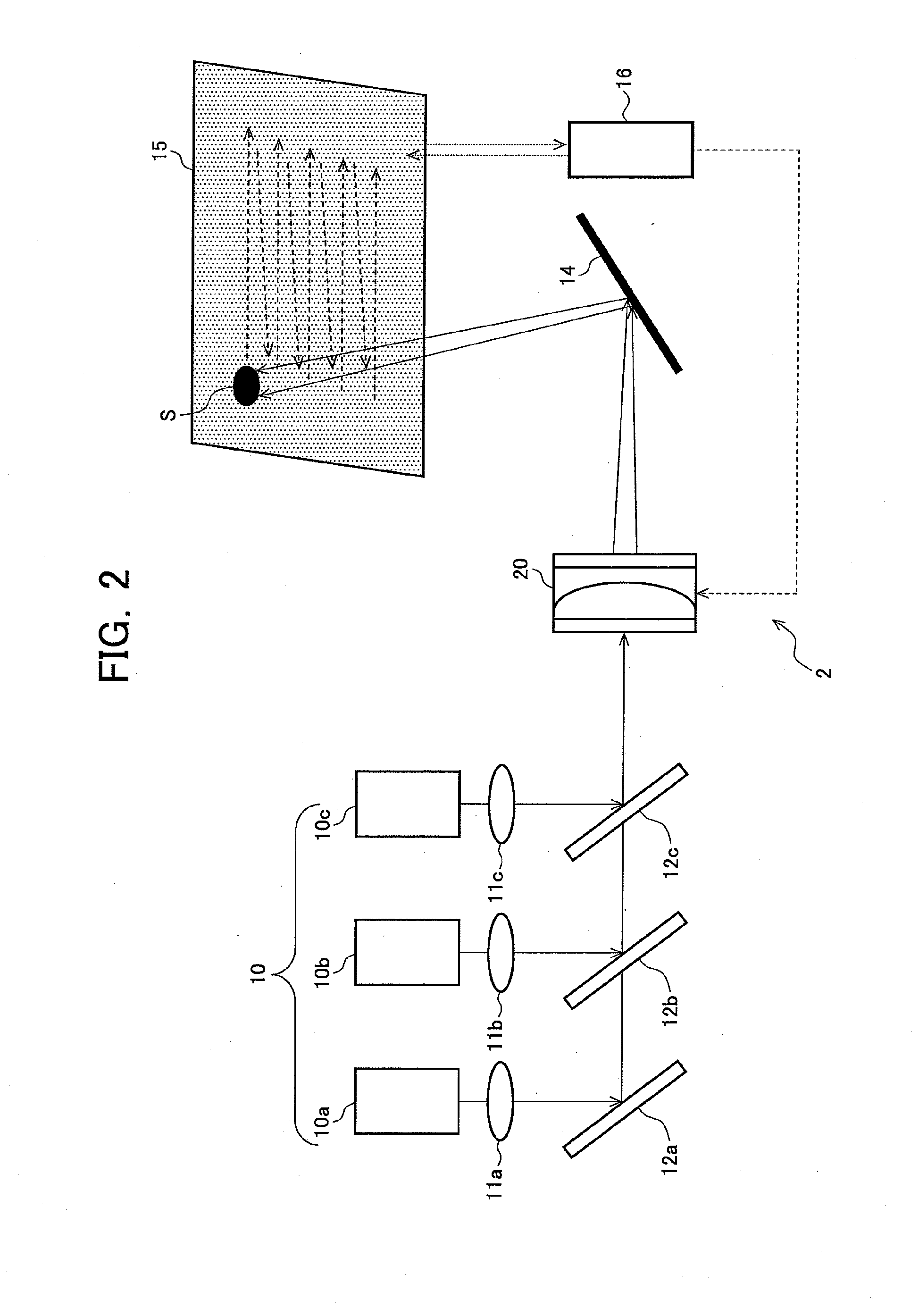
[0057]FIG. 2 is a diagram of an exemplary configuration of an image display apparatus according to a second embodiment of the present invention and, in FIG. 2, 2 denotes an image display apparatus. In FIG. 2, the same portions as those in the image display apparatus 1 of the first embodiment are denoted by the same reference numerals and will briefly be described by omitting a part of the description including application examples. The description for the method of improving image quality in accordance with a projection size is also the same as that for the first embodiment.

[0058]The image display apparatus 2 depicted in FIG. 2 is made up of the laser light source device 10 made up of the laser light sources 10a to 10c of R, G, and B, the collimating lenses 11a to 11c that collimate output light beams into parallel lights, the dichroic mirrors 12a to 12c that only reflect wavelengths of their respective light beams, a variable focus device 20 including a liquid lens, the MEMS mirror...

third embodiment

[0063]FIG. 3 is a diagram of an exemplary configuration of an image display apparatus according to a third embodiment of the present invention and, in FIG. 3, 3 denotes an image display apparatus. In FIG. 3, the same portions as those in the image display apparatus 1 of the first embodiment are denoted by the same reference numerals and will briefly be described by omitting a part of the description including application examples. The description for the reduction of the image quality deterioration due to the projection size is also the same as that of the first embodiment.

[0064]FIG. 4 is a diagram of an exemplary configuration of a variable focus device according to the image display apparatus of FIG. 3 and FIG. 5 is a diagram of an example of arrangement of pixels formed on a screen under control of the variable focus device of FIG. 4.

[0065]The image display apparatus 3 depicted in FIG. 3 is made up of the laser light source device 10 made up of the laser light sources 10a to 10c ...


PUM


Abstract

Provided is an image display apparatus which can reduce the influence of image quality degradation caused by a spot size on a screen generated when using a light source having a high directivity such as a laser beam and scan-type image formation means. The image display apparatus includes: a light source device (10) which emits light; scan-type image formation means (such as an MEMS mirror (14)) which forms an image on a screen (15); a variable focus device (13) arranged in the optical path of the light emitted from the light source device (10) to reach the image formation means; and control means which controls the variable focus device (13) so as to modify the spot size of the light beam projected onto the screen (15) in accordance with a projected image size or an user operation.

Description

TECHNICAL FIELD[0001]The present invention relates to an image display apparatus, and, more particularly, to an image display apparatus using a highly directional light source such as a laser beam.BACKGROUND OF THE INVENTION[0002]A projector (projection type image display apparatus) exists that displays an image by applying light from a light source device to a spatial light modulation element such as a liquid crystal panel for projecting the light on a screen. Conventionally, a lamp such as a high-pressure mercury lamp or a metal halide lamp is used as a light source of a projection type image display apparatus.[0003]However, such a lamp has not only problems that a life time is short and that a long time is required for turning on but also requires an optical system for separating three primary colors of red, green, and blue from a light source, problems of low efficiency of use of light, complicated structure, and poor color reproducibility.[0004]To solve these problems, an image...

Claims


Application Information

Patent Timeline
Patent Type & Authority Applications(United States)
IPC IPC(8): G03B21/28G03B21/14
CPCG02B26/0816G02B26/0875H04N9/3129H04N9/317G02B3/14G03B21/005
Inventor ARITA, SHINICHI
Owner SHARP KK
Why Eureka
Try Eureka