Emitter for x-ray tubes and heating method therefore

a technology of x-ray tubes and emitters, which is applied in the manufacture of discharge tubes/lamps, electrode systems, discharge tube main electrodes, etc., can solve the problems of enlarged focal spots and strong optical aberration, and achieve the effect of reducing the deformation of the emitting area, increasing the optical quality of the emitter, and improving the compensation of the elongation of the emitting section/emitting area

Active Publication Date: 2010-12-16
KONINKLIJKE PHILIPS ELECTRONICS NV
View PDF11 Cites 35 Cited by
  • Summary
  • Abstract
  • Description
  • Claims
  • Application Information

AI Technical Summary

Benefits of technology

[0016]According to another preferred embodiment of the invention, the fixing sections have a spring structure. Due to the fact that one major problem of an unstructured flat emitter is the thermal expansion, the spring structure of the fixing sections may compensate this expansion. This compensation could lead to a significantly reduced deformation of the emitting area and thus to a further increased optical quality of the emitter.
[0017]According to an exemplary embodiment of the present invention, each fixing section is connected with a corner of the emitting section. This arrangement of the fixing sections allows to apply a mechanical pretension in a way, that the elongation of the emitting area during its hot phase is compensated. ...

Problems solved by technology

The disadvantage however may also based on the structuring: The electrical field may penetrates into the slit and the potential lines therefore bend into the slit region.
If an electron is emitted from the surfac...

Method used


Image

  • Emitter for x-ray tubes and heating method therefore
  • Emitter for x-ray tubes and heating method therefore
  • Emitter for x-ray tubes and heating method therefore

Examples


Embodiment Construction

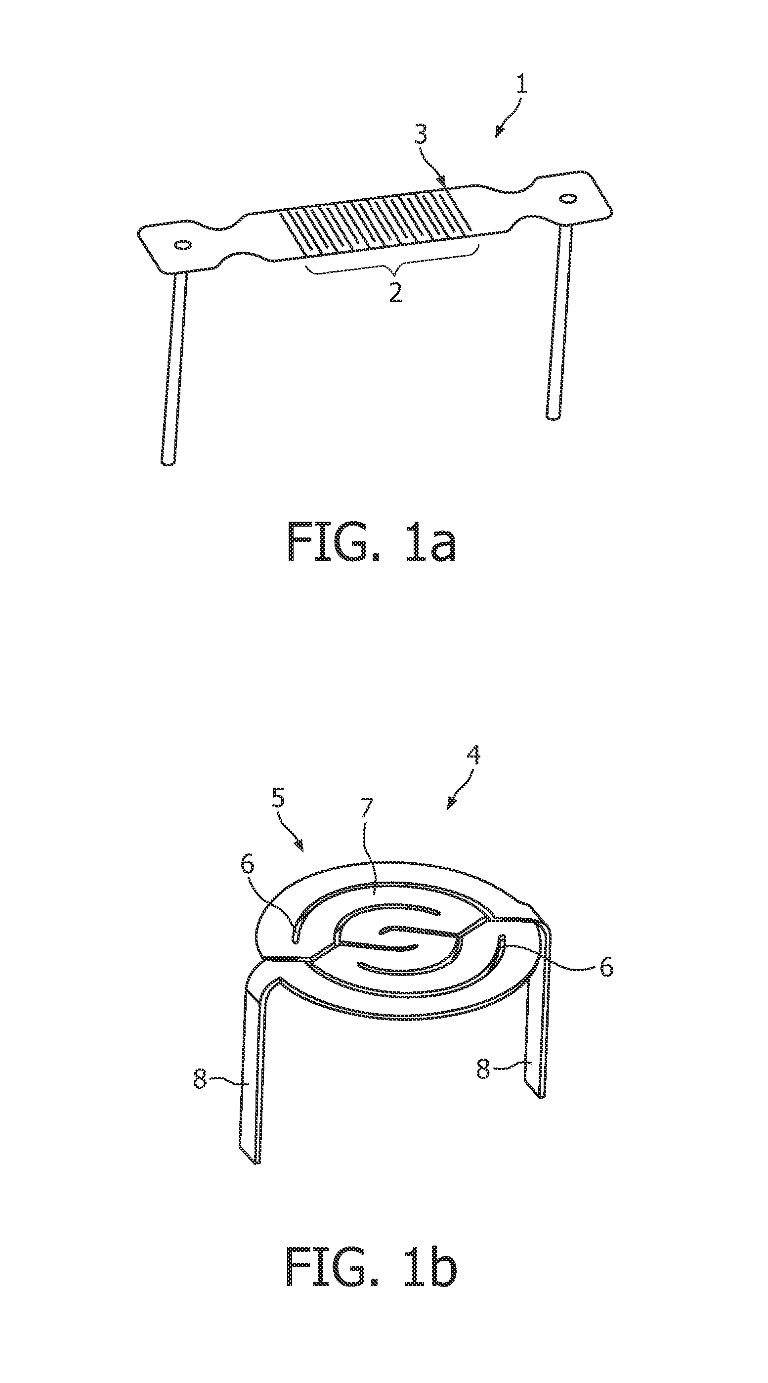
[0047]A directly heated thin flat emitter 1 with a rectangular emitting surface 2, as known from the art, is shown in FIG. 1a). To create an electric current path the emitter design uses slits 3.

[0048]Even the emitter 4 of FIG. 1b) with a round emitting surface 5 uses slits 6 and is directly heated. The flat emitting surface 5 is subdivided by the slits into spiral conductor sections 7. Further, FIG. 1b) shows formed legs 8, as FIG. 1a), which here are angled 90° for installation and simultaneously serve as support elements via a heating current and the cathode high voltage are applied.

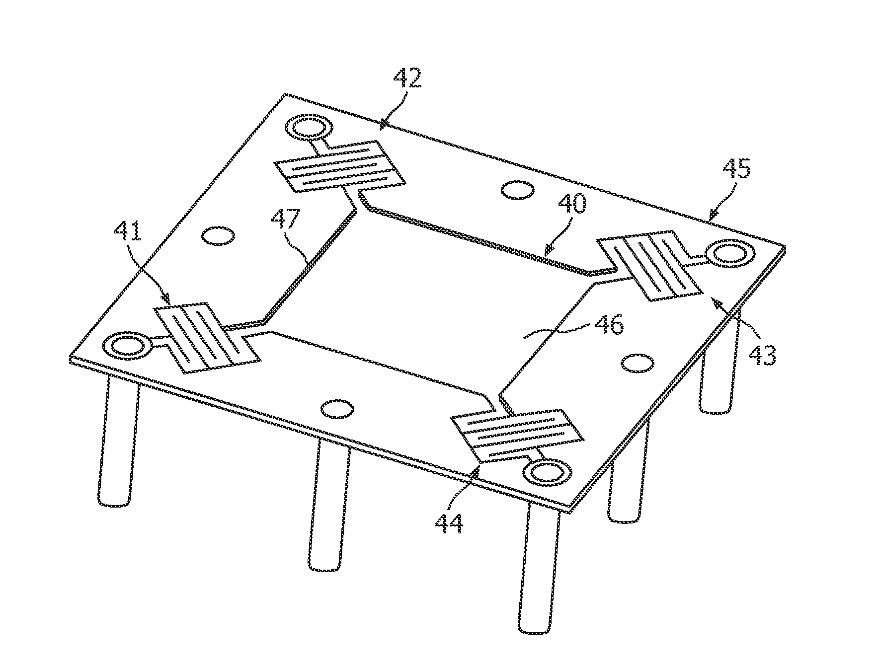
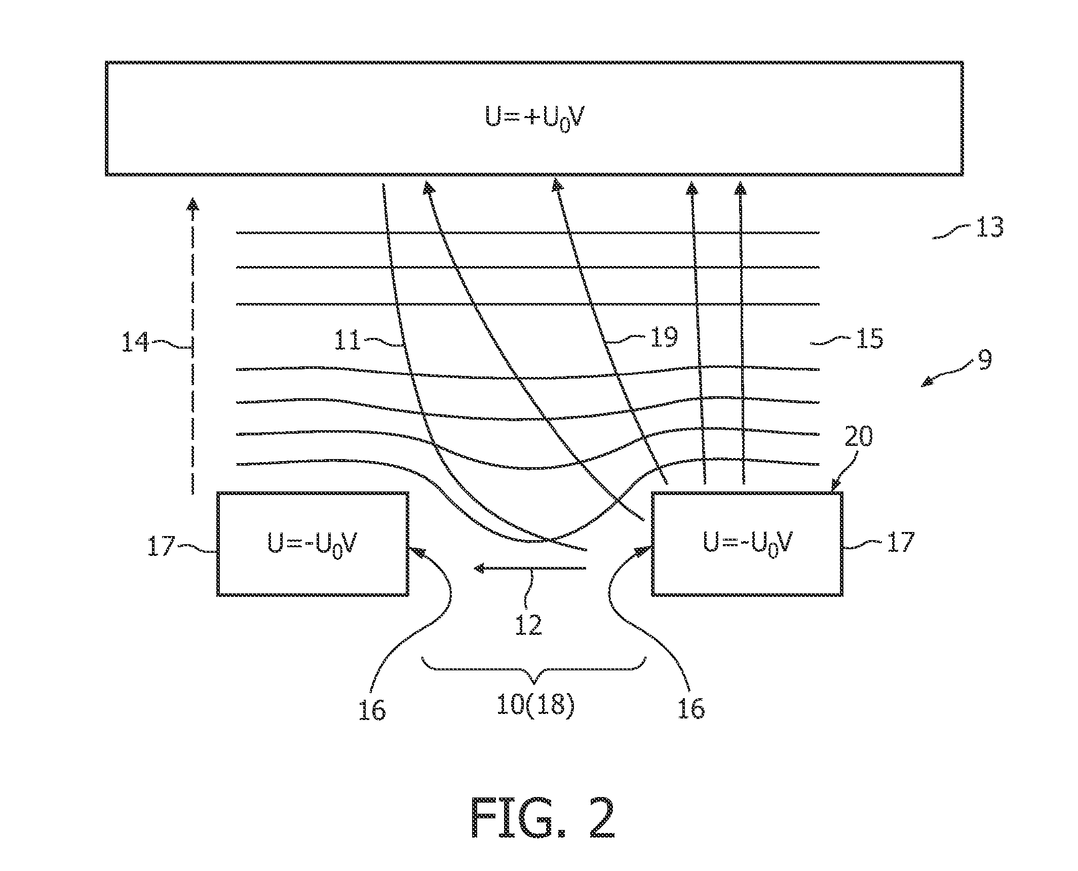
[0049]FIG. 2 shows an example of a structured directly heated flat emitter (DHFE) of the state of the art. Especially, the influence of a slit structure 10 of an emitter 9, as e.g. shown in FIG. 1a) and FIG. 1b) to the tracks of the electrons (arrows 11) from negative to positive potential are shown in FIG. 2: The electrons get higher tangential energy components (arrow 12) in relation to an optical a...


PUM


Abstract

It is described an emitter (26, 40) for X-ray tubes comprising: a flat foil with an emitting section (30, 46); and at least two electrically conductive fixing sections (31-34; 41-44); wherein the emitting section (30, 46) is unstructured.

Description

FIELD OF THE INVENTION[0001]The present invention relates to the field of fast high-current electron sources for X-ray tubes. In particular, the present invention relates to an emitter for X-ray tubes, further, a heating device for the emitter, a setup consisting of the emitter and the heating device and a heating method to heat the emitter.ART BACKGROUND[0002]The future demands for high-end CT and CV imaging regarding the X-ray source are higher power / tube current, shorter response-times regarding the tube current (pulse modulation) and smaller focal spots (FS) for higher image quality.[0003]One key to reach higher power in smaller FS is given by using a sophisticated electron optical concept. But of same importance are the electron source itself and the starting condition of the electrons.[0004]For today's high-end tubes directly heated thin flat emitters are used that are structured to define an electrical path and to obtain the required high electrical resistance. Basically, two...

Claims


Application Information

Patent Timeline
IPC IPC(8): H01J35/06
CPCH01J35/06H01J2201/2803H01J35/064
Inventor HAUTTMANN, STEFANMARING, WOLFRAM
Owner KONINKLIJKE PHILIPS ELECTRONICS NV
Why Eureka
Try Eureka