Techniques for controlling a light source in a wavelength division multiplexed passive optical network

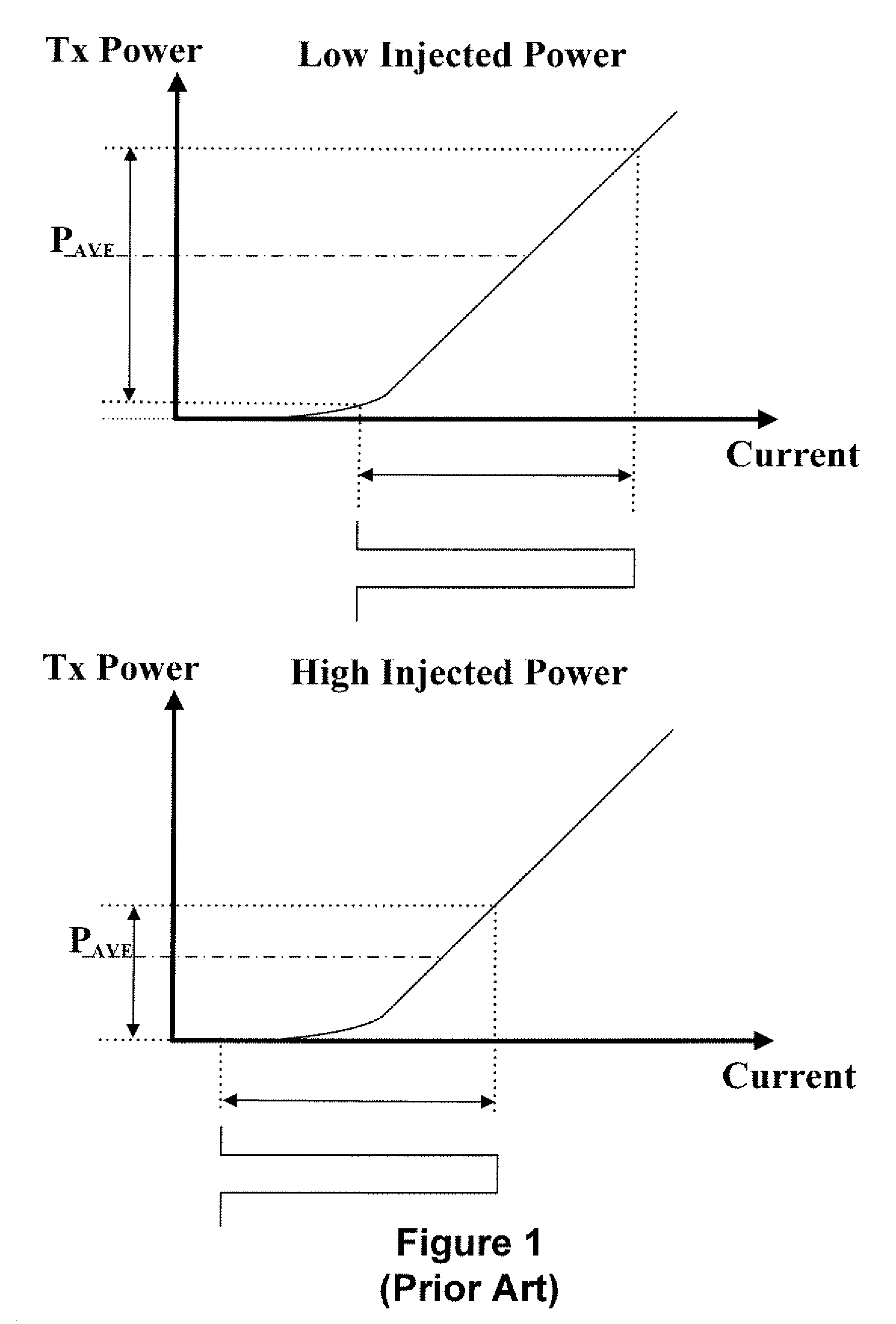
a technology of wavelength division multiplexing and light source, applied in the direction of wavelength-division multiplex system, transmission monitoring, multiplex communication, etc., can solve the problem that the average output power (psub>avg/sub>) detected by the monitoring photodiode (mpd) may not be an accurate representation of the output power of the light source, and the optical eye may be distorted

Active Publication Date: 2010-12-16
LG ERICSSON
View PDF6 Cites 27 Cited by
  • Summary
  • Abstract
  • Description
  • Claims
  • Application Information

AI Technical Summary

Problems solved by technology

However, several drawbacks are associated with detecting the average output power (PAVG) of the light sources In particular, the average output power (PAVG) detected by the monitoring photodiode (MPD) may not be an accurate representation of an output power of the light source.
The monitoring photodiode (MPD) may detect a high average output power (PAVG) from the light source (e.g., because of the high injection power) and may erroneously instruct the controlling circuit to bias the light source below a threshold voltage and / or current (e.g., putting the light source in an OFF-state) and thus decrease the transmitted power.
Also, by erroneously biasing the light source below a threshold voltage and / or current, an optical eye may be distorted due to a delay when turning the light source ON and OFF.
In view of the foregoing, it may be understood that there may be significant problems and shortcomings associated with current wavelength division multiplexed passive optical network (WDM-PON) technologies using seed injected Fabry Perot laser diode (FP-LD) and / or a reflective semiconductor optical amplifier (RSOA) transmitter source.

Method used


Image

  • Techniques for controlling a light source in a wavelength division multiplexed passive optical network
  • Techniques for controlling a light source in a wavelength division multiplexed passive optical network
  • Techniques for controlling a light source in a wavelength division multiplexed passive optical network

Examples


Embodiment Construction

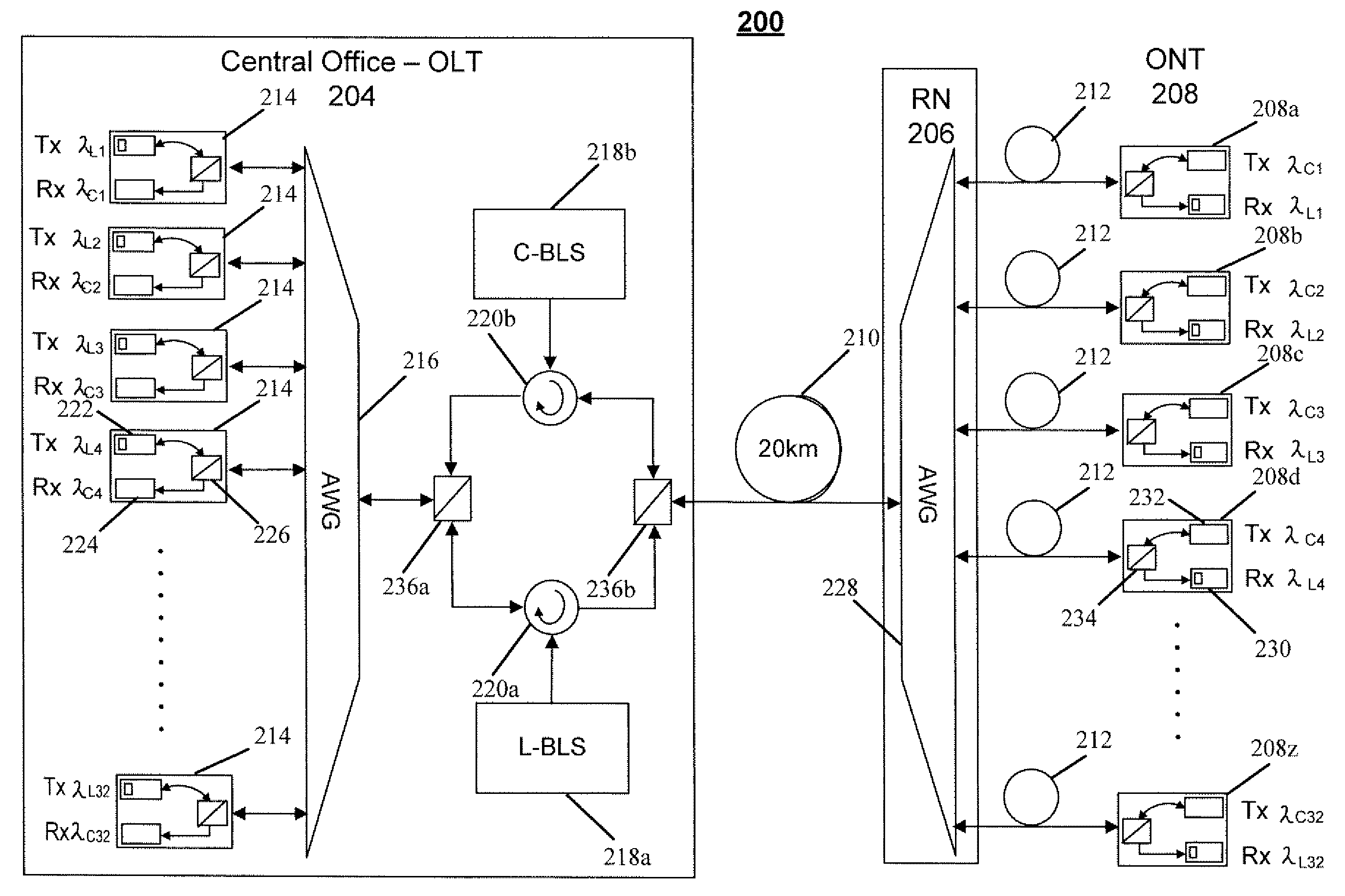
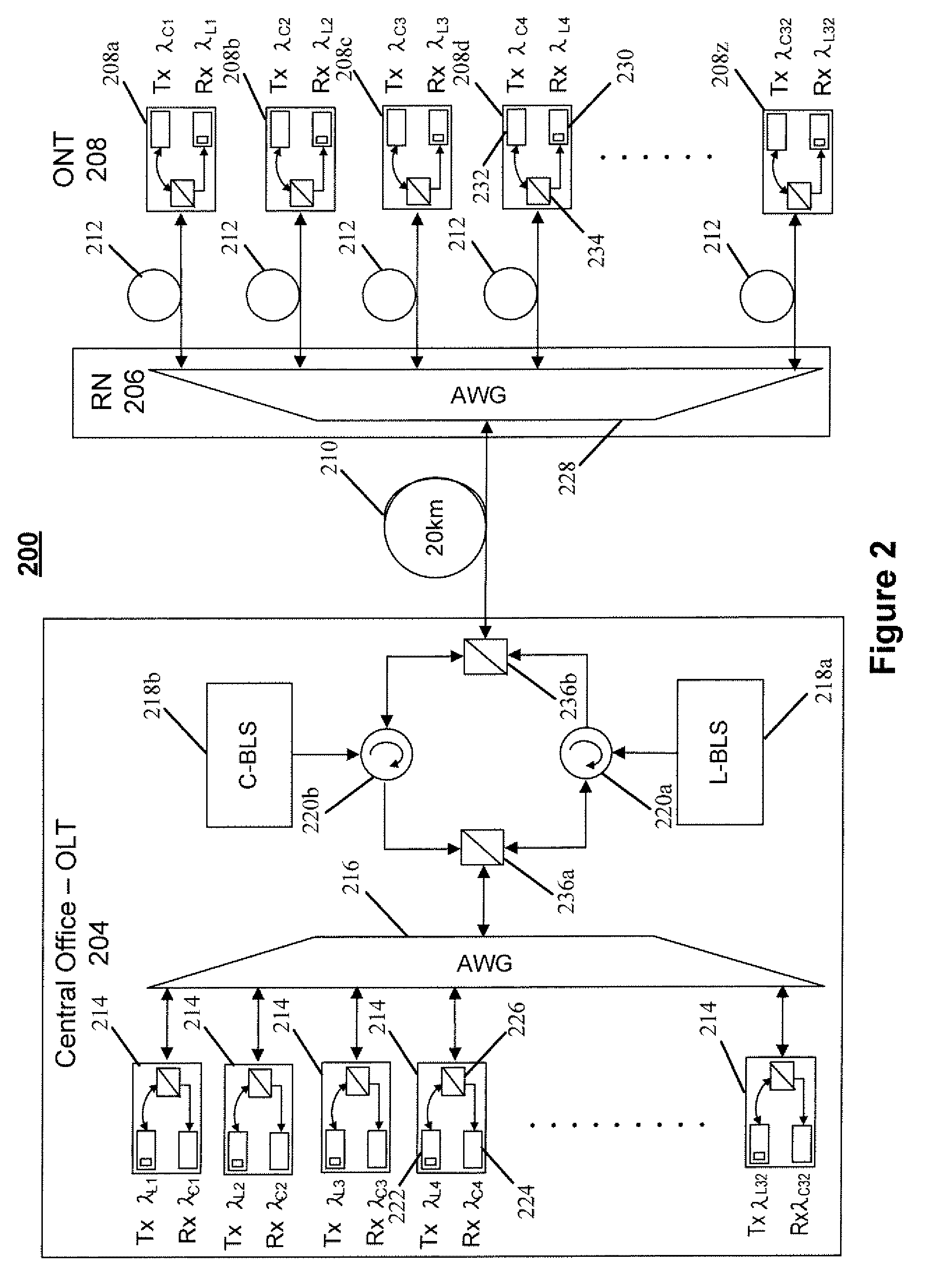
[0036]Referring to FIG. 2, there is shown an embodiment of a wavelength division multiplexed passive optical network (WDM-PON) 200 in accordance with an embodiment of the present disclosure. That is, the wavelength division multiplexed passive optical network (WDM-PON) 200 may comprise an optical line terminal (OLT) 204 (e.g., a central office of a telecommunications service provider) coupled to a remote node (RN) 206 (e.g., a multiplexer / demultiplexer) via an optical fiber 210. The remote node (RN) 206 may be coupled to a plurality of optical network terminals (ONTs) 208 via a plurality of optical fibers 212. Each of the plurality of optical network terminals (ONTs) 208 may maintain a connection with one or more customers (not shown) for facilitating telecommunications services between these customers and a telecommunications service provider.

[0037]The optical line terminal (OLT) 204 may include a plurality of transceiver assemblies 214, a multiplexer / demultiplexer 216 (e.g., 1×N w...


PUM


Abstract

Techniques for controlling a light source in a wavelength division multiplexed passive optical network (WDM-PON) are disclosed. In one particular exemplary embodiment, the techniques may be realized as an apparatus for controlling a light source in a wavelength division multiplexed passive optical network (WDM-PON). The apparatus may include a digital signal processing device configured to output a pilot tone signal. The apparatus may also include an amplifier configured to modulate a modulation current and the pilot tone signal, and output an amplitude modulated signal. The apparatus may further include a capacitor configured to AC couple the amplitude modulated signal to a bias current applied to a light source; and a monitoring photodiode configured to detect an output optical signal of the light source and transmit the detected output optical signal to the digital signal processing device to control the output optical signal of the light source.

Description

FIELD OF THE DISCLOSURE[0001]The present disclosure relates generally to wavelength division multiplexed passive optical networks and, more particularly, to techniques for controlling a light source in a wavelength division multiplexed passive optical network (WDM-PON).BACKGROUND OF THE DISCLOSURE[0002]Over the last few decades, telecommunications carriers have been considering an inexpensive means of using optical fibers to support access to telecommunications services over a last mile of connection between residential and business customers and a central office of a telecommunications service provider. The greatest bandwidth requirement for telecommunications services for these customers is typically not greater than a couple of gigabits per second (Gbps). To support this bandwidth requirement, studies have shown that wavelength division multiplexed passive optical networks (WDM-PONs) are the access technology that has attracted the most interest and shown the greatest commercial ...

Claims


Application Information

Patent Timeline
Patent Type & Authority Applications(United States)
IPC IPC(8): H04J14/02H04B10/2581H04B10/43
CPCH04B10/2587H04B10/506H04J14/0221H04J14/0282H04B10/2581H04B10/43H04J14/02
Inventor LUK, TOMBAINBRIDGE, JOHN
Owner LG ERICSSON
Why Eureka
Try Eureka