
Method For Pulling A Silicon Single Crystal

a single crystal and silicon technology, applied in the direction of polycrystalline material growth, silicon compounds, under protective fluids, etc., can solve the problems of yield loss which is commensurately more serious, concentrated in single crystals, advantageous, etc., and achieves substantial reduction of yield loss and yield loss

Active Publication Date: 2010-12-16
SILTRONIC AG
View PDF10 Cites 4 Cited by
  • Summary
  • Abstract
  • Description
  • Claims
  • Application Information

AI Technical Summary

Benefits of technology

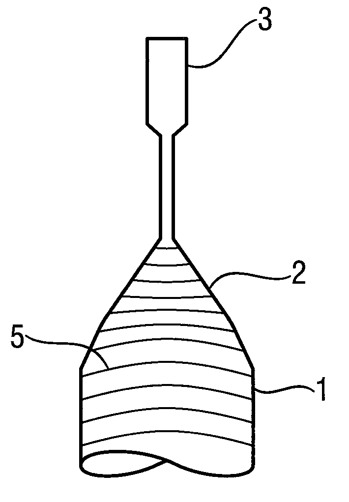
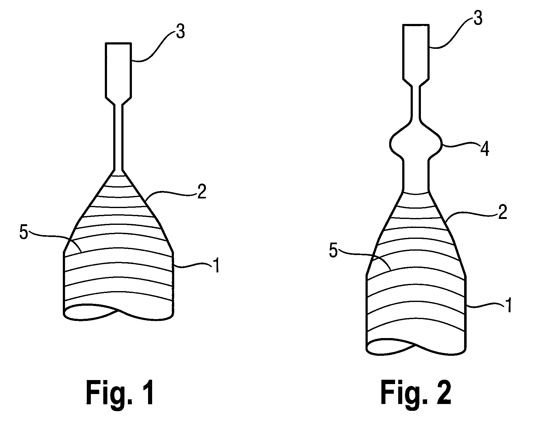
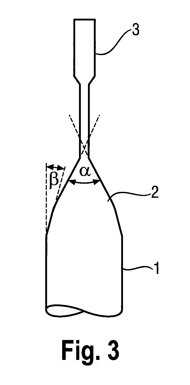
[0005]In pulling a silicon single crystal from the melt, a seed crystal is immersed into the melt and raised, material of the melt being crystallized on the seed crystal to form a single crystal. After a stabilization phase, first a neck section is pulled and later a conical section is pulled, the diameter of the growing single crystal being widened to a setpoint diameter during pulling of the conical section. The melt not only contains silicon, but conventionally also one or more dopants which are intended to be incorporated in the lattice of the single crystal in order to determine the electrical conductivity of the single crystal. The melt furthermore contains oxygen, which is dissolved from the crucible material and partially incorporated into the single crystal. The oxygen contained in the single crystal has advantageous and disadvantageous effects.
[0006]Precipitates containing oxygen, i.e. so-called BMDs (bulk micro-defects), act as internal getters which can bind metallic impurities and thereby prevent them from interfering with the functions of electronic components. High oxygen concentrations, on the other hand, also promote the formation of detrimental stacking faults, so-called OSFs (oxidation-induced stacking faults). It is therefore desirable to control the oxygen concentration in the single crystal, and likewise the concentration of dopants, so that they do not depart from a narrowly specified concentration range at least in the region of the single crystal's cylindrical section which is used for the production of semiconductor wafers, has the setpoint diameter, and is adjacent to the conical section.
[0007]The oxygen concentration in the single crystal can be influenced in various ways, for example by controlling the gas pressure in the reactor, by controlling the speed with which inert gas is fed through the reactor, by controlling the distance between the melt surface and the lower end of a heat shield enclosing the single crystal, by controlling the rotation speed of the single crystal and the crucible, and by controlling the strength of a magnetic field applied to the melt. Despite the use of such control measures, there are problems in obtaining the oxygen concentration in the specified concentration range from the start, i.e. at the beginning of the cylindrical section of the single crystal. If the semiconductor wafers obtained from the start of the cylindrical section of the single crystal do not have the oxygen concentration specified by the customer, this leads to a yield loss which is commensurately more serious when the diameter of the single crystal is larger and when its cylindrical section is shorter.SUMMARY
[0008]It is an object of the present invention to provide a method, with the aid of which such yield losses can be substantially reduced. These and other objects are achieved by a method for pulling a silicon single crystal from a melt which is contained in a crucible, comprising immersion of a seed crystal into the melt; crystallizing the single crystal on the seed crystal by raising the seed crystal from the melt with a crystal pull speed; and widening the diameter of the single crystal to a setpoint diameter in a conical section, wherein the crystal pull speed is controlled in such a way so as to induce a curvature inversion of a growth front of the single crystal in the conical section.

Problems solved by technology

The oxygen contained in the single crystal has advantageous and disadvantageous effects.
Despite the use of such control measures, there are problems in obtaining the oxygen concentration in the specified concentration range from the start, i.e. at the beginning of the cylindrical section of the single crystal.
If the semiconductor wafers obtained from the start of the cylindrical section of the single crystal do not have the oxygen concentration specified by the customer, this leads to a yield loss which is commensurately more serious when the diameter of the single crystal is larger and when its cylindrical section is shorter.

Method used


Image

  • Method For Pulling A Silicon Single Crystal
  • Method For Pulling A Silicon Single Crystal
  • Method For Pulling A Silicon Single Crystal

Examples


example

[0023]A silicon single crystal having a nominal setpoint diameter of 200 mm was pulled according to the invention. The profile of the crystal pull speed expressed in terms of the initial speed, i.e. V(rel), in the region of the conical section is shown in FIG. 4. The relative diameter of the conical section in relation to the setpoint diameter, i.e. D(rel), is plotted as the abscissa.

[0024]For comparison, another single crystal was pulled with the same nominal diameter but with a virtually constant crystal pull speed while pulling the conical section. In this single crystal, the region at the start of the cylindrical section did not comply with the predetermined specification with respect to the oxygen concentration. There was no such yield loss in the case of the single crystal pulled according to FIG. 4.


PUM

PropertyMeasurementUnit
apex angleaaaaaaaaaa
external angleaaaaaaaaaa

Abstract

The invention relates to a method for pulling a silicon single crystal from a melt which is contained in a crucible, comprising immersion of a seed crystal into the melt; crystallization of the single crystal on the seed crystal by raising the seed crystal from the melt with a crystal pull speed; widening the diameter of the single crystal to a setpoint diameter in a conical section, comprising control of the crystal pull speed in such a way as to induce a curvature inversion of a growth front of the single crystal in the conical section.

Description

CROSS-REFERENCE TO RELATED APPLICATIONS[0001]This application claims priority to German Patent Application No. 10 2009 024 473.5 filed Jun. 10, 2009 which is herein incorporated by reference.BACKGROUND OF THE INVENTION[0002]1. Field of the Invention[0003]The invention relates to a method for pulling a silicon single crystal from a melt which is contained in a crucible.[0004]2. Background Art[0005]In pulling a silicon single crystal from the melt, a seed crystal is immersed into the melt and raised, material of the melt being crystallized on the seed crystal to form a single crystal. After a stabilization phase, first a neck section is pulled and later a conical section is pulled, the diameter of the growing single crystal being widened to a setpoint diameter during pulling of the conical section. The melt not only contains silicon, but conventionally also one or more dopants which are intended to be incorporated in the lattice of the single crystal in order to determine the electric...

Claims


Application Information

Patent Timeline
Patent Type & Authority Applications(United States)
IPC IPC(8): C01B33/02C30B15/22
CPCC30B15/22C30B29/06Y02P80/30
Inventor BAER, MARKUS
Owner SILTRONIC AG
Learn More