Exhaust Gas Treatment System Including an HC-SCR and Two-way Catalyst and Method of Using the Same

a technology of exhaust gas treatment system and catalyst, which is applied in the direction of exhaust treatment electric control, machines/engines, mechanical equipment, etc., can solve the problems of reducing the target nosub>x /sub>reduction level during vehicle operation, and limited commercial application of lean-operating engines

Inactive Publication Date: 2010-12-23
GM GLOBAL TECH OPERATIONS LLC
View PDF30 Cites 61 Cited by
  • Summary
  • Abstract
  • Description
  • Claims
  • Application Information

AI Technical Summary

Benefits of technology

[0006]In one exemplary embodiment of the present invention, an exhaust gas treatment system for a diesel engine is provided. The exhaust gas treatment system includes a hydrocarbon selective catalytic reduction catalyst (HC-SCR) in fluid communication with a diesel engine to receive an exhaust gas flow therefrom. The system also includes a two-way catalyst in fluid communication with the HC-SCR to receive the exhaust gas flow therefrom, the two-way catalyst comprising a urea selective catalytic reduction catalyst and a diesel particulate filter (DPF).

Problems solved by technology

When an engine operates with a lean (excess oxygen) air / fuel ratio, the resultant combustion temperature and excess oxygen leads to higher engine-out NOX; however, commercial application of lean-operating engines is limited due to lack of effective methods to remove NOX from an exhaust gas flow under lean exhaust conditions.
Reduction of NOX emissions from an exhaust feedstream containing excess oxygen is a challenge for vehicle manufacturers.
However, such systems require periodic catalyst regeneration involving fuel injection to generate high exhaust gas temperatures and injection of reductants to regenerate the storage material of the catalyst.
During periods of catalyst regeneration, maintaining the targeted NOX reduction levels during operation of the vehicle becomes problematic, since the components being regenerated will have greatly reduced NOX conversion capability.

Method used


Image

  • Exhaust Gas Treatment System Including an HC-SCR and Two-way Catalyst and Method of Using the Same
  • Exhaust Gas Treatment System Including an HC-SCR and Two-way Catalyst and Method of Using the Same
  • Exhaust Gas Treatment System Including an HC-SCR and Two-way Catalyst and Method of Using the Same

Examples


Embodiment Construction

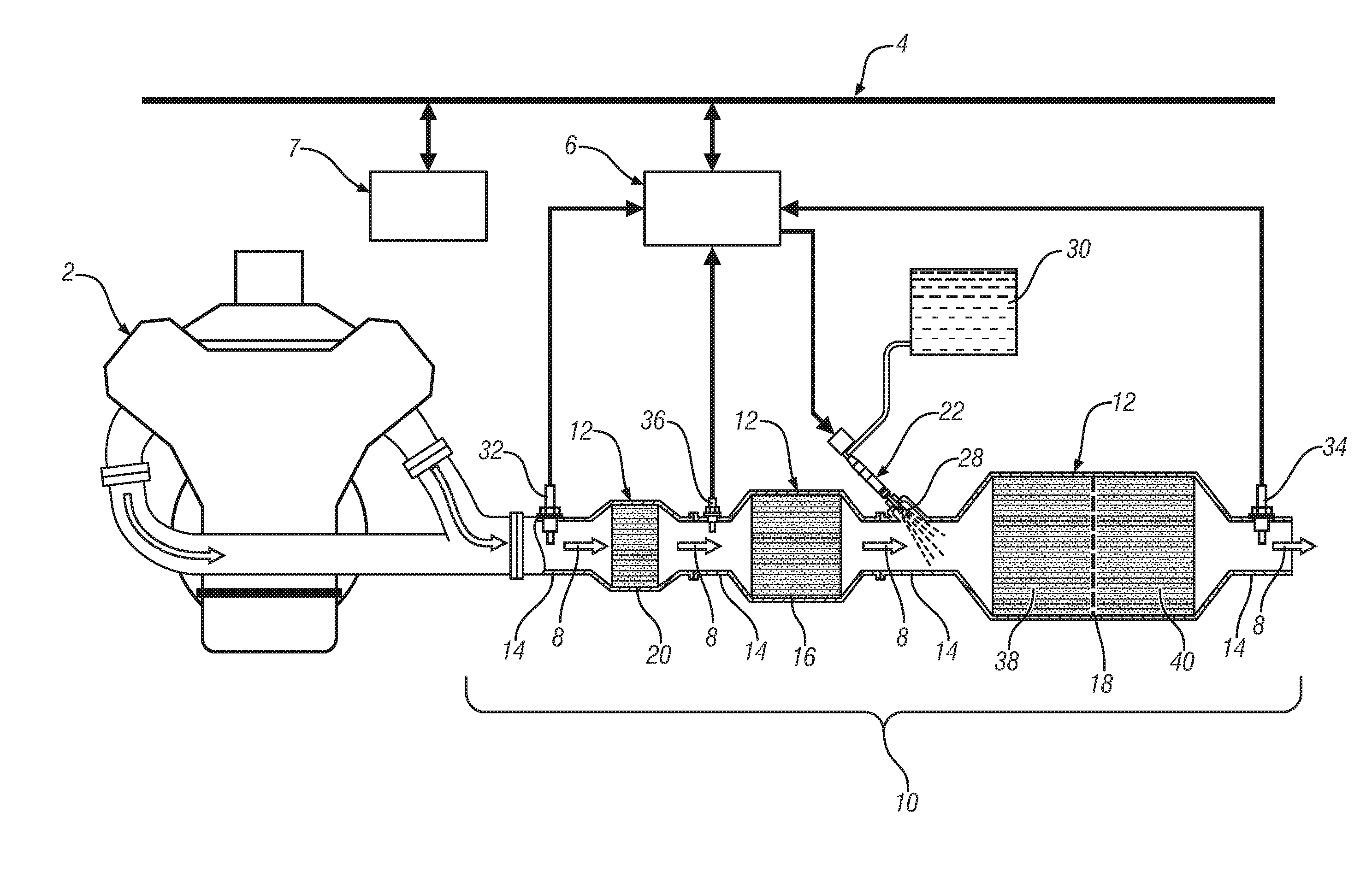
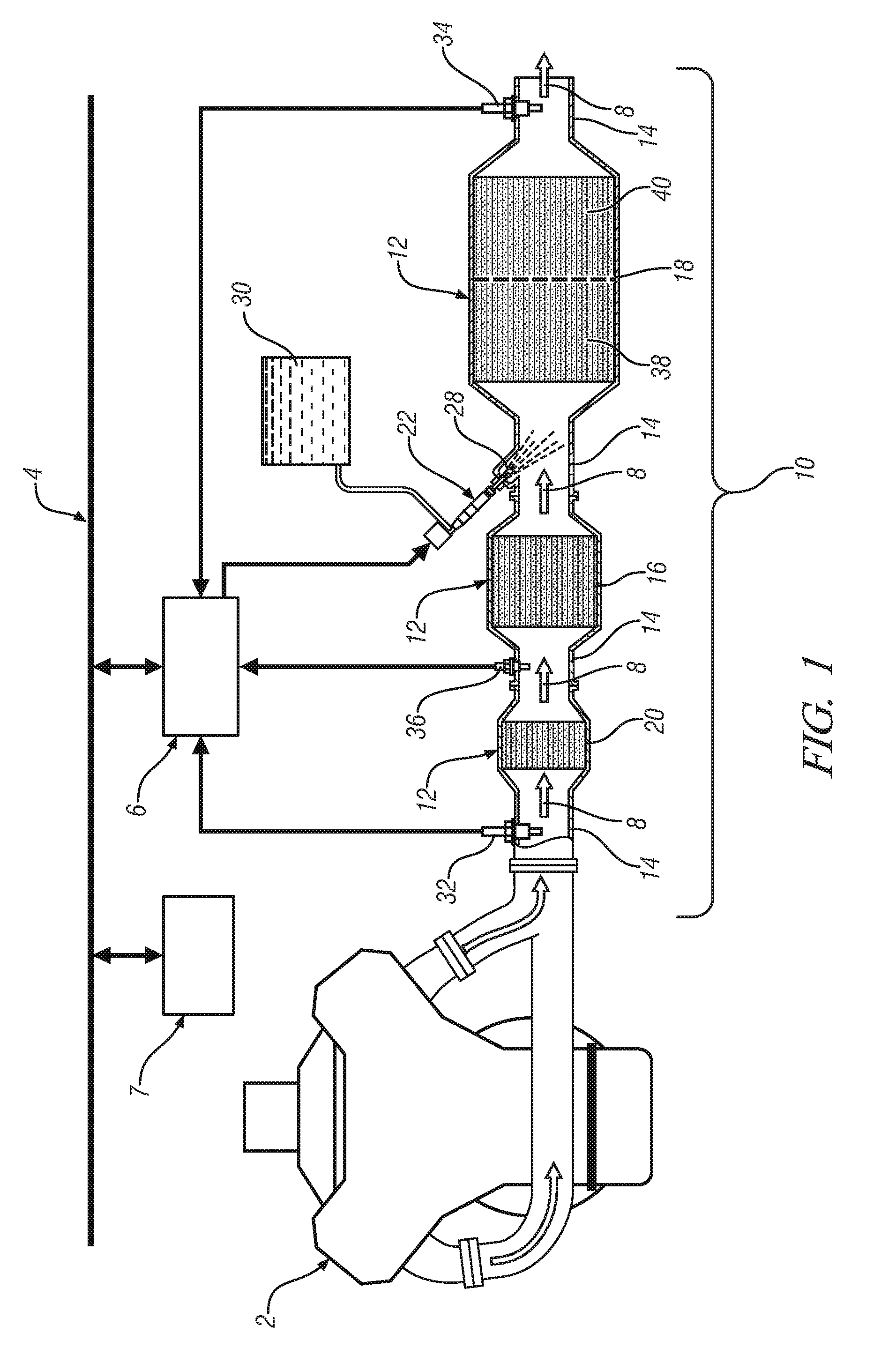
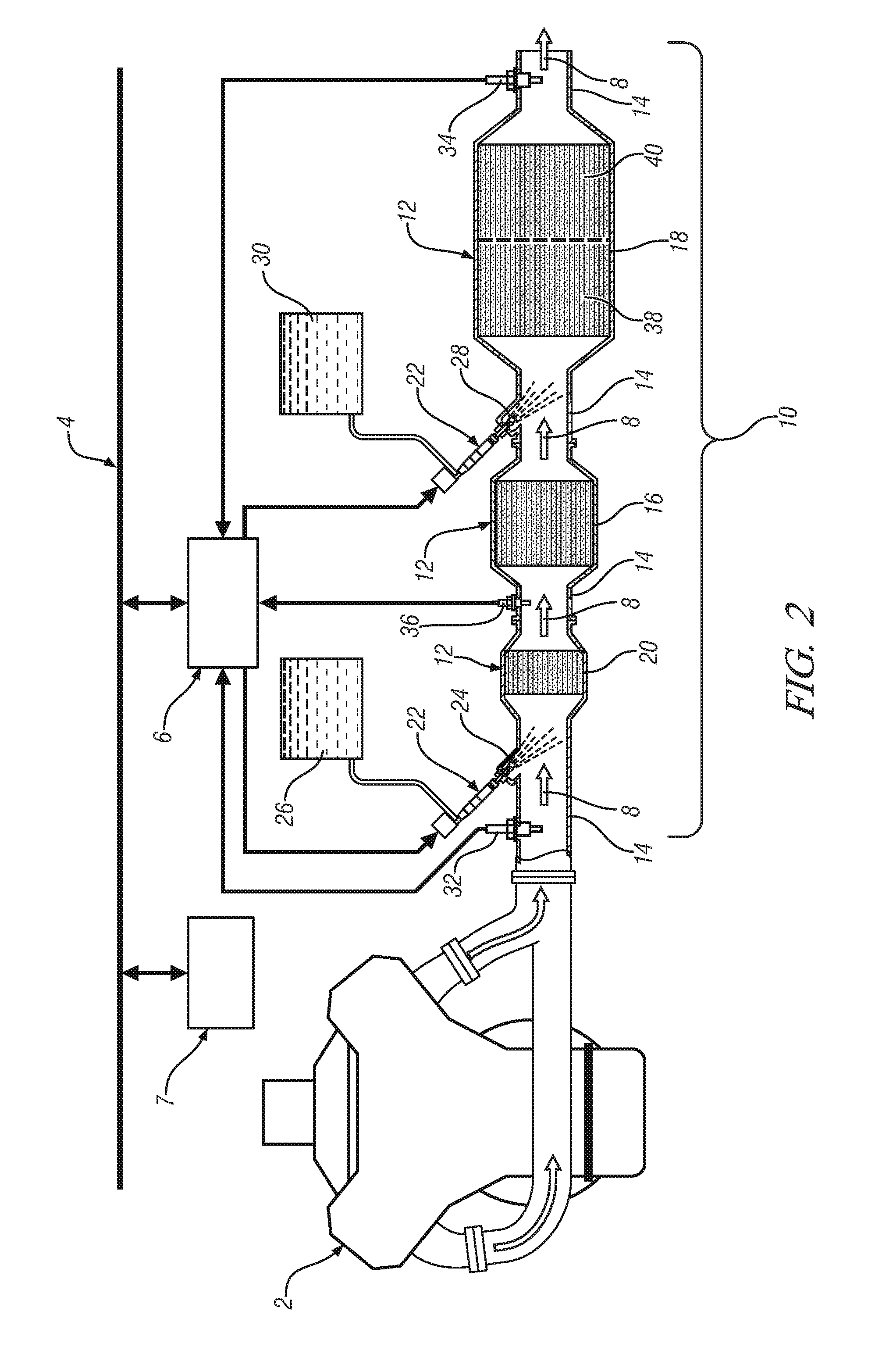
[0018]In accordance with exemplary embodiments of the present invention, improved exhaust gas treatment systems and methods for treatment of exhaust gas emissions from diesel engines are provided. The present invention provides the potential for reduced and controlled exhaust emissions, including emissions of NOX, CO, HC and diesel particulates (PM), while improving overall packaging for the exhaust gas treatment system. The present invention also provides the potential for enhanced emission control strategies and methods, including strategies and methods, for example, that minimize the consumption of hydrocarbon (e.g., fuel) or urea needed to achieve reduced exhaust emissions, or that minimize the need for regeneration to remove accumulated sulfur compounds, and thereby extend the operating life of the exhaust system components. This is achieved through the use of advantageous combinations of exhaust system components or devices that are particularly suited for synergistic interact...


PUM


Abstract

An exhaust gas treatment system for a diesel engine is disclosed. The exhaust gas treatment system includes a hydrocarbon selective catalytic reduction catalyst (HC-SCR) in fluid communication with a diesel engine to receive an exhaust gas flow therefrom. The system also includes a two-way catalyst in fluid communication with the HC-SCR to receive the exhaust gas flow therefrom, the two-way catalyst comprising a urea selective catalytic reduction catalyst and a diesel particulate filter (DPF).

Description

FIELD OF THE INVENTION[0001]Exemplary embodiments of the present invention are related to exhaust gas treatment systems, and, more specifically, to an exhaust gas treatment system for a diesel engine and a method of using the same.BACKGROUND[0002]Manufacturers of internal combustion engines develop engine operation control strategies to satisfy customer demands and meet various regulations for emission control and fuel economy. One such engine control strategy comprises operating an engine at an air / fuel ratio that is lean of stoichiometry to improve fuel economy and reduce greenhouse gas emissions. Such operation is possible using both compression-ignition (diesel) and spark-ignition engines. When an engine operates with a lean (excess oxygen) air / fuel ratio, the resultant combustion temperature and excess oxygen leads to higher engine-out NOX; however, commercial application of lean-operating engines is limited due to lack of effective methods to remove NOX from an exhaust gas flo...

Claims


Application Information

Patent Timeline
Patent Type & Authority Applications(United States)
IPC IPC(8): F01N9/00F01N3/035F01N3/10
CPCF01N3/021F01N3/2066F01N3/2073F01N2250/04F01N2560/026Y02T10/24F01N2570/10F01N2570/14F01N2610/02F01N2610/03Y02C20/10F01N2560/06Y02T10/12
Inventor MITAL, RAHUL
Owner GM GLOBAL TECH OPERATIONS LLC
Why Eureka
Try Eureka