Gas turbine combustor
- Summary
- Abstract
- Description
- Claims
- Application Information
AI Technical Summary
Benefits of technology
Problems solved by technology
Method used
Image
Examples
first embodiment
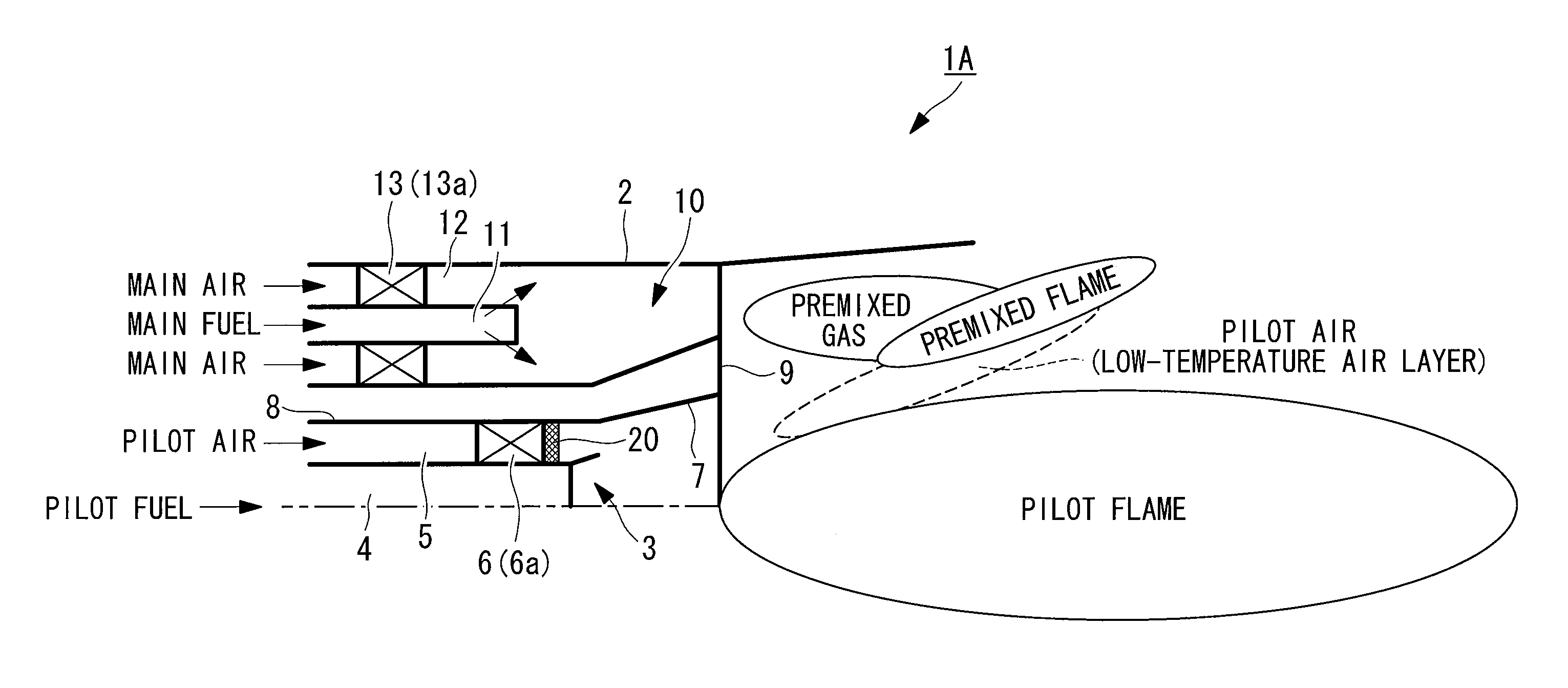
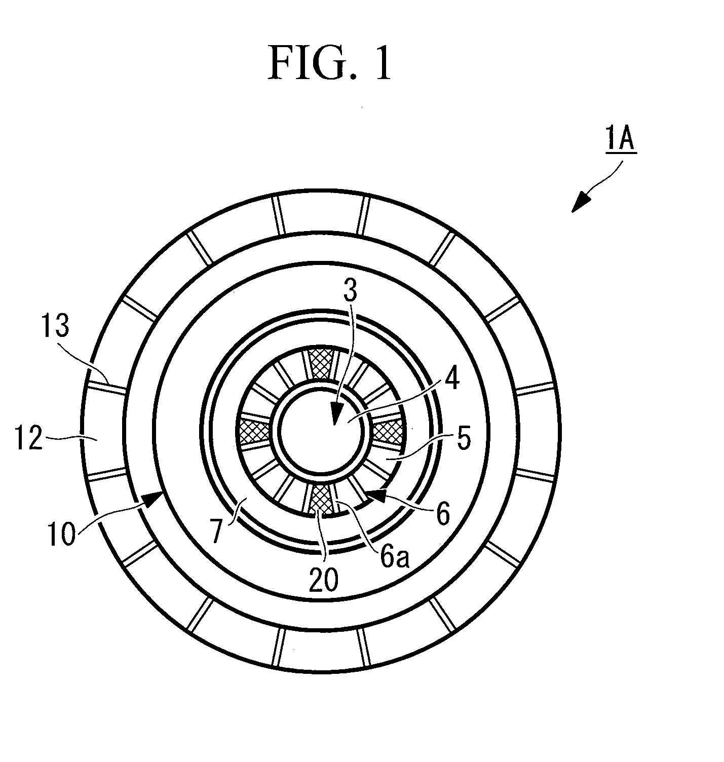
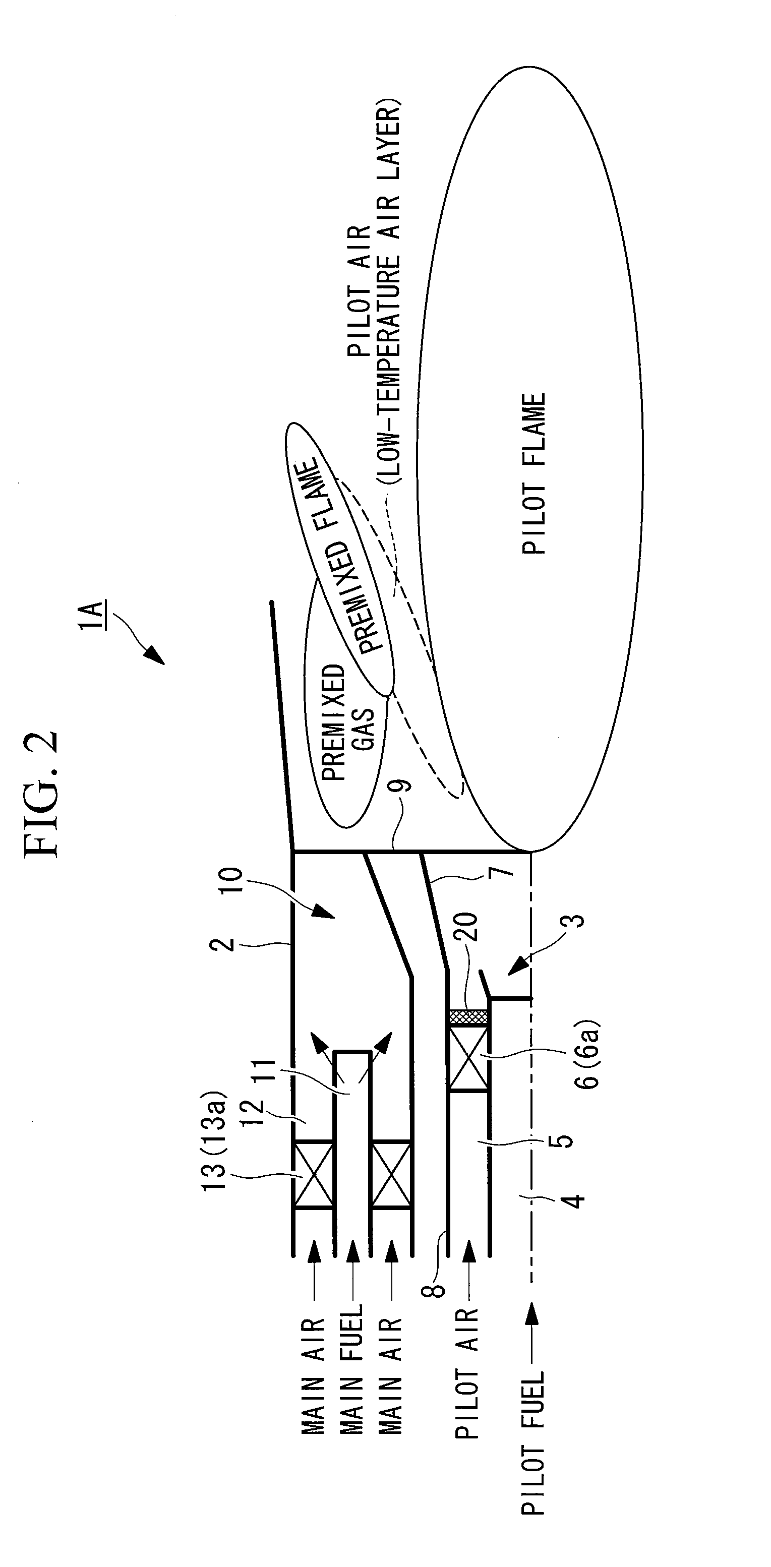
[0064]A gas turbine combustor 1A shown in FIG. 1 and FIG. 2 has a configuration in which a pilot burner 3 is provided at the center position of a combustor main body 2 formed in a cylindrical shape, and a plurality of (for example, eight) main burners 10 are provided at a uniform pitch in the circumferential direction so as to surround the periphery of this pilot burner 3.
[0065]The pilot burner 3 is provided with a pilot nozzle 4 that supplies pilot fuel and a pilot air channel 5 that is formed around the pilot nozzle 4 and supplies pilot air thereto. The pilot fuel supplied through the pilot nozzle 4 is combusted with the pilot air supplied from the pilot air channel 5 and, as shown in FIG. 2 for example, forms a pilot flame extending rearward of a flame stabilizer 9 from the combustor axial center.
[0066]A pilot swirler 6 that makes the flow of the pilot air become a swirling flow is disposed inside the above-described pilot air channel 5. This pilot swirler 6 partitions the interi...
second embodiment
[0077]Next, for the gas turbine combustor according to the present invention, a second embodiment will be described based on FIG. 4 and FIG. 5. Note that, in the following description, parts similar to those in the above-described embodiment are assigned the same reference numerals, and a detailed description thereof will thus be omitted.
[0078]In this embodiment, a gas turbine combustor 1B is provided with one or a plurality of plate-like projecting members 21 projecting rearward from the outer edge of the pilot cone 7 as the ignition improving part. In the illustrated configuration, four plate-like projecting members 21 arranged at a 90-degree pitch in the circumferential direction are provided so as to project from the rear end of the pilot cone 7 towards the rear flame forming region. In other words, the cylindrical member 8 of this embodiment employs the pilot cone 7 having plate members 21 at the rear end.
[0079]By attaching such plate-like projecting members 21, the flow of the...
third embodiment
[0082]Next, for the gas turbine combustor according to the present invention, a third embodiment will be described based on FIG. 6A to FIG. 6C. In a gas turbine combustor 10 in FIG. 6A used here, the outer peripheral side main burner is omitted, and only the pilot burner is illustrated. Note that, in the following description, parts similar to those in the above-described embodiments are assigned the same reference numerals, and a detailed description thereof will thus be omitted.
[0083]In this embodiment, as the ignition improving part, wedge-shaped vortex generators 22 having a sweepback angle are provided at one or a plurality of positions on the inner peripheral surface of the locations corresponding to the outer edge of the pilot cone 7. In the illustrated configuration, four wedge-shaped vortex generators 22 arranged at a 90-degree pitch in the circumferential direction are provided on the inner peripheral surface of the outer edge of the pilot cone 7. In other words, the cylin...
PUM
 Abstract
Description
Claims
Application Information
 - R&D
- Intellectual Property
- Life Sciences
- Materials
- Tech Scout
- Unparalleled Data Quality
- Higher Quality Content
- 60% Fewer Hallucinations
Browse by: Latest US Patents, China's latest patents, Technical Efficacy Thesaurus, Application Domain, Technology Topic, Popular Technical Reports.
© 2025 PatSnap. All rights reserved.Legal|Privacy policy|Modern Slavery Act Transparency Statement|Sitemap|About US| Contact US: help@patsnap.com


