Self-excited oscillating flow heat pipe

a heat pipe and self-excitation technology, which is applied in the direction of indirect heat exchangers, lighting and heating apparatus, etc., can solve the problems of significant heat transport performance decline, difficult operation of heat pipes, and inability to secure the space for a large-sized heat sink to be installed right above the central processing unit. achieve the effect of high heat transportation performan

Inactive Publication Date: 2010-12-23
NAT UNIV CORP YOKOHAMA NAT UNIV
View PDF15 Cites 6 Cited by
  • Summary
  • Abstract
  • Description
  • Claims
  • Application Information

AI Technical Summary

Benefits of technology

[0013]According to the self-excited oscillating flow heat pipe of the invention, it is possible to provide a self-excited oscillating flow heat pipe capable of exhibiting high heat transportation performance even if the heat pipe is horizontally installed, without making a tube meander.

Problems solved by technology

However, for example, when miniaturization of electronic apparatuses, such as a notebook-type personal computer, is carried out, for example, it becomes impossible to secure the space for a large-sized heat sink to be installed right above the central processing unit (CPU), which is a heat source.
In such a heat pipe, the maximum heat transport rate in a case where the heat pipe has an outside diameter of about 3 mm, and is installed horizontally is about 12 W. However, the wick-type heat pipe has a problem that heat transport performance significantly decline, when the tube diameter is decreased (made small).
However, in a meandering loop-type self-excited oscillating flow heat pipe (inside diameter of about 0.5 mm to 2 mm), which is a representative example of the above heat pipe, there are problems in that it is necessary to make a number of tubes meander, and operation of the heat pipe is difficult when horizontally installed (refer to Nonpatent Document 1).

Method used


Image

  • Self-excited oscillating flow heat pipe
  • Self-excited oscillating flow heat pipe
  • Self-excited oscillating flow heat pipe

Examples


example 1

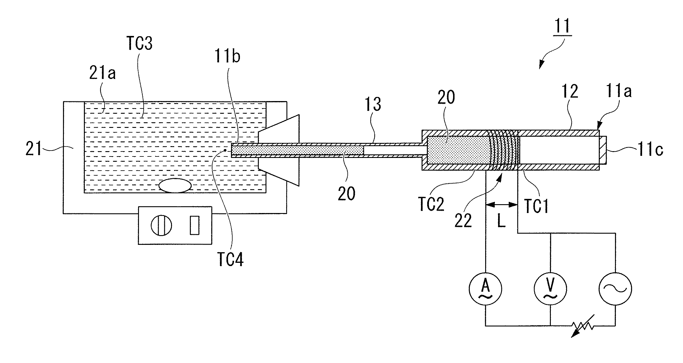
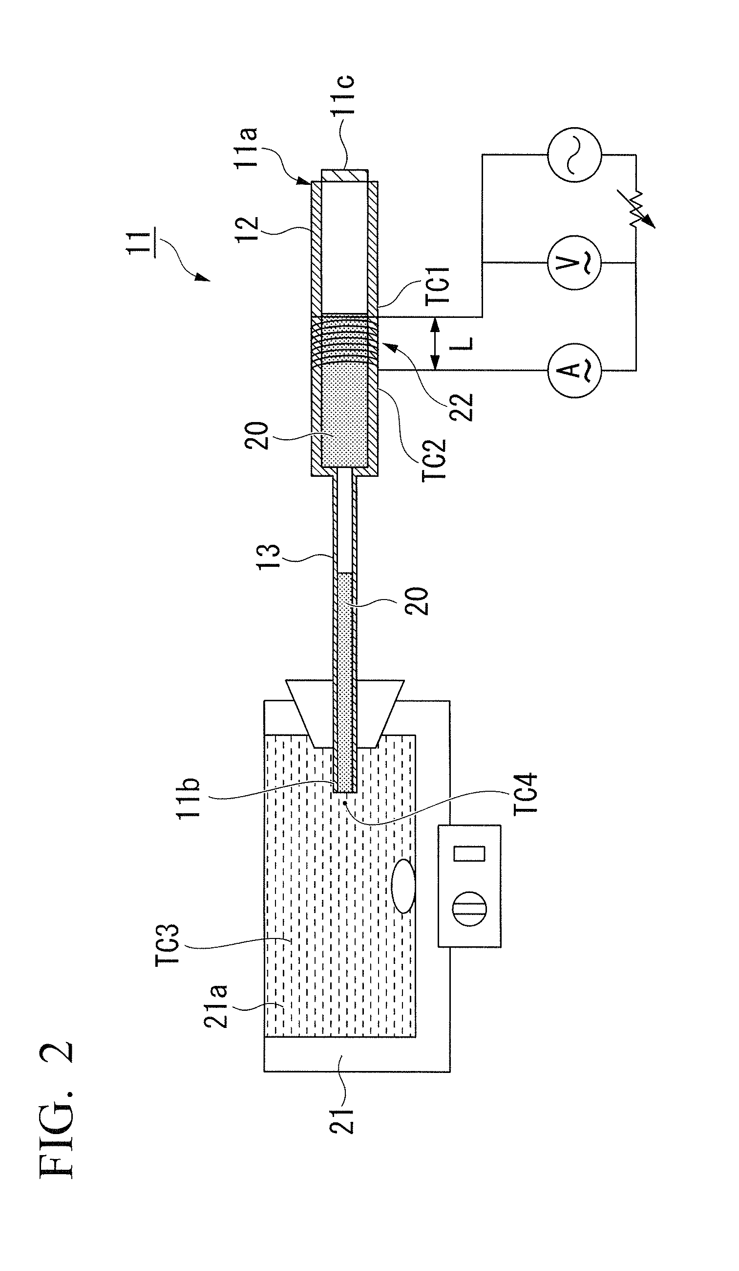
[0067]Characteristics of a heat pipe were evaluated by an experimental device shown in FIG. 2.

[0068]First, a glass tube 13 used as the connection channel 5 made of borosilicate glass with an inside diameter of 2 mm and a length of 250 mm, and a glass tube 12 used as the heating unit 2 made of borosilicate glass with an inside diameter of 5 mm and a length of 150 mm were prepared, and the glass tubes 12 and 13 were fused together. Next, the wick 14 made of a copper net was mounted on the inner wall of the glass tube 12. The wick 14 was mounted at a distance of 100 mm from the fused portion. The portion mounted with the wick 14 was used as the heating unit 2. Next, sealing by a sealing member 11c of which one end 11a is made of borosilicate glass was performed. Next, an open end 11b of the glass tube 13 used as the connection channel was immersed in a water bath 21, and the insides of the glass tubes 12 and 13 were filled with pure water used as the working fluid 20. The heat pipe 11 ...

example 2

[0077]Next, a heat pipe of Example 2 was fixed up similarly to Example 1 except that quartz glass was used as the material for a heating-side pipe and a cooling-side pipe. Then, similarly to Example 1, the relationship between the heat transport rate Q and the effective thermal conductivity λeff in the heat pipe of Example 1 was investigated. The results are shown in FIG. 5.


PUM


Abstract

A self-excited oscillating flow heat pipe includes a heating unit having a wick therein; a cooling unit filled with a working fluid; a connection channel which rectilinearly connects the heating unit with the cooling unit, and has a smaller channel cross-sectional area than the channel cross-sectional area of the heating unit; a liquid plug protruding into the connection channel from the cooling unit and containing the working fluid; and a vapor plug in the heating unit containing the vaporized working fluid. The liquid plug oscillates self-excitedly in the connection channel.

Description

TECHNICAL FIELD[0001]The present invention relates to a self-excited oscillating flow heat pipe.[0002]Priority is claimed on Japanese Patent Application No. 2008-029713 filed on Feb. 8, 2008, the content of which is incorporated herein by reference.BACKGROUND ART[0003]In recent years, with miniaturization and high integration of electronic devices, the heat generation density of semiconductor elements has been rapidly increasing, and establishment of an efficient heat removal technique has become imperative. However, for example, when miniaturization of electronic apparatuses, such as a notebook-type personal computer, is carried out, for example, it becomes impossible to secure the space for a large-sized heat sink to be installed right above the central processing unit (CPU), which is a heat source. In such a case, it is necessary to transport generated heat to a location where the heat sink can be installed. For this reason, a wick-type heat pipe is utilized as a heat transport m...

Claims


Application Information

Patent Timeline
Patent Type & Authority Applications(United States)
IPC IPC(8): F28D15/04
CPCF28D15/04F28D15/0266
Inventor OKUYAMA, KUNITOMORI, SHOUJI
Owner NAT UNIV CORP YOKOHAMA NAT UNIV
Why Eureka
Try Eureka