Heat exchanger with a mixing chamber

Inactive Publication Date: 2010-12-23
DELPHI TECH INC
View PDF4 Cites 20 Cited by
  • Summary
  • Abstract
  • Description
  • Claims
  • Application Information

AI Technical Summary

Benefits of technology

[0008]An object of the invention is to provide a heat exchanger with a more uniform distribution of the first fluid to the tubes and a m

Problems solved by technology

Nonetheless, the fluid circulation in the collector box is not optimized.
More particularly, the two phases flow is not homogeneously mixed creating pressure drops and ef

Method used


Image

  • Heat exchanger with a mixing chamber
  • Heat exchanger with a mixing chamber
  • Heat exchanger with a mixing chamber

Examples


Embodiment Construction

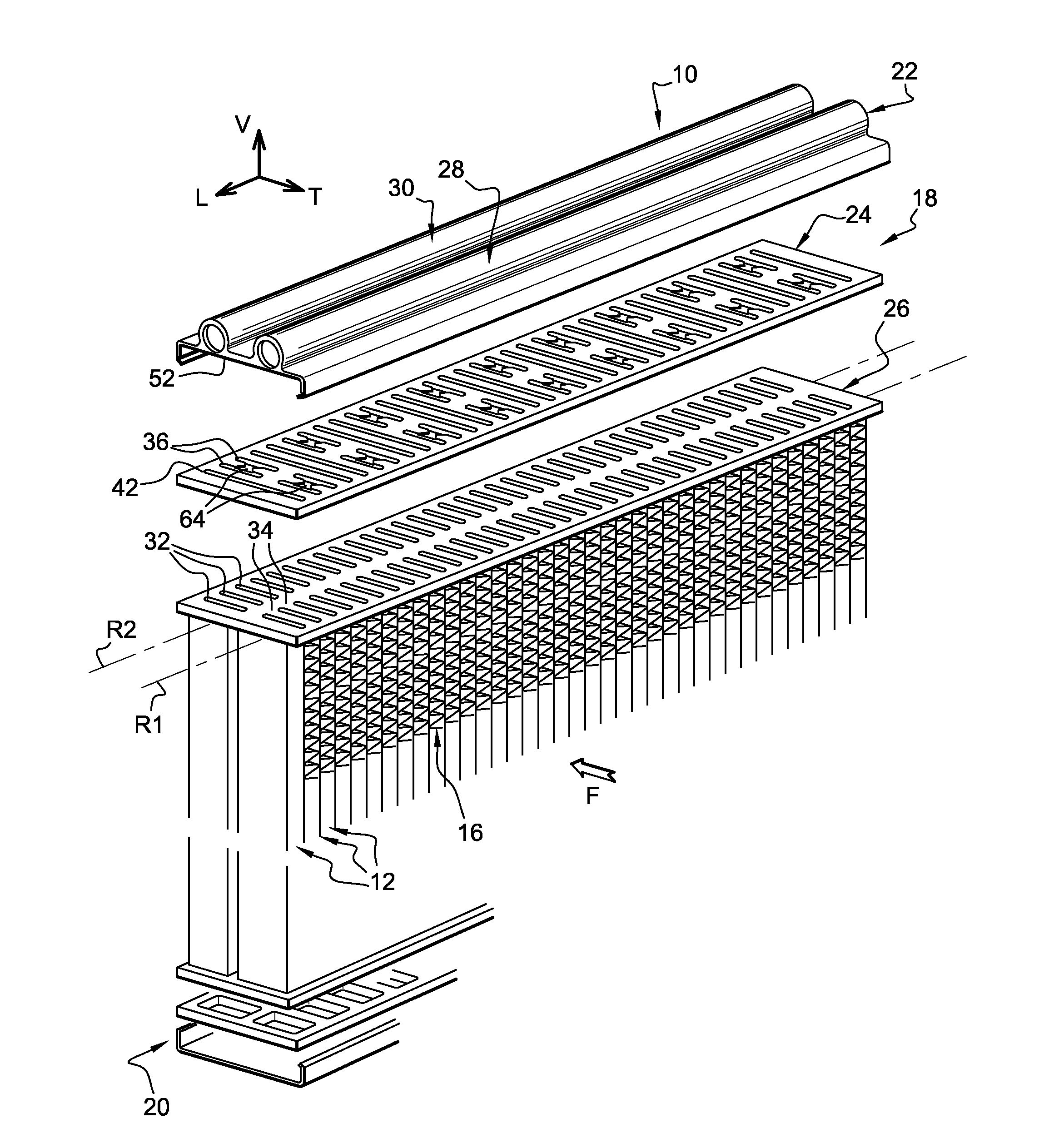
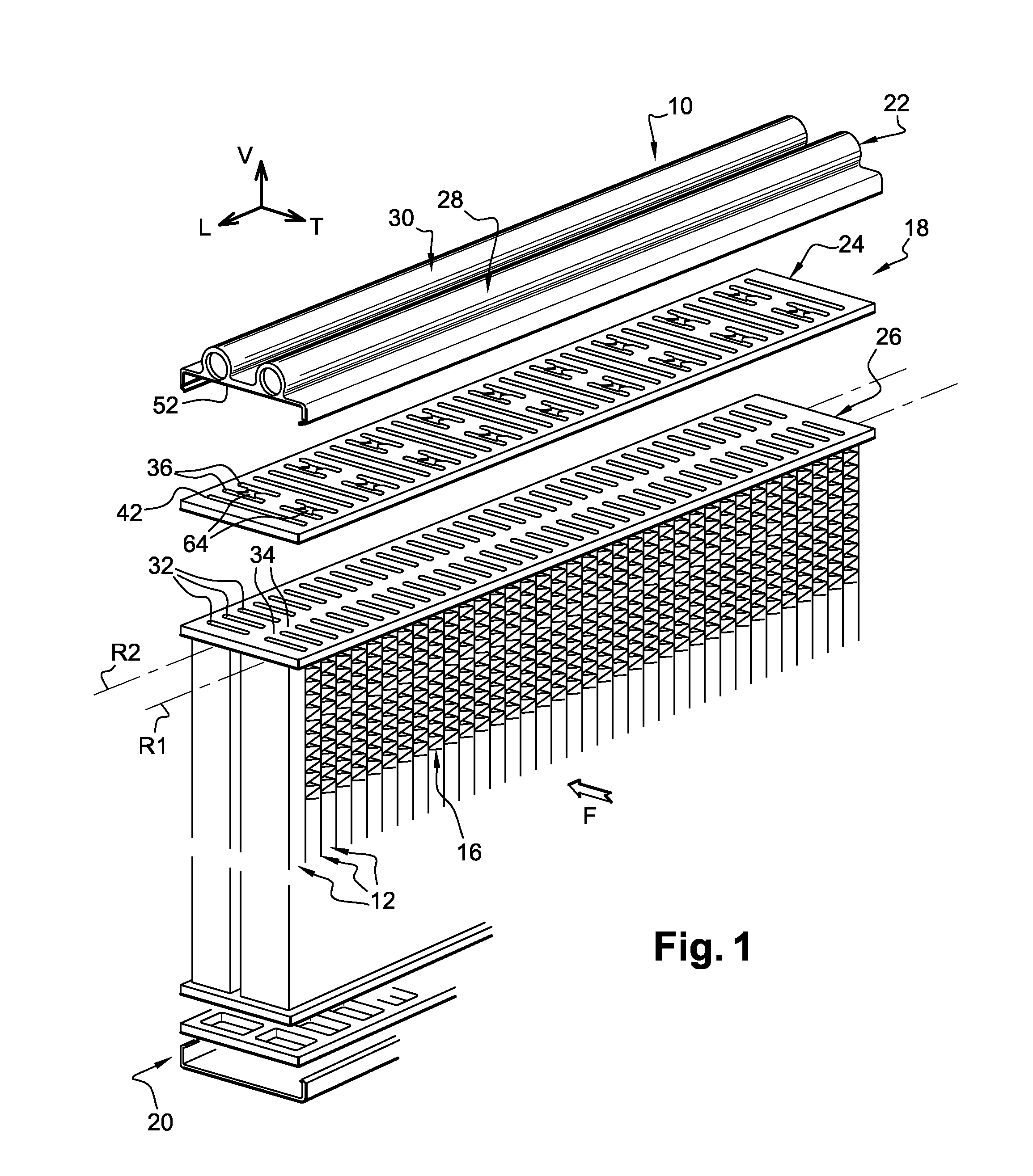
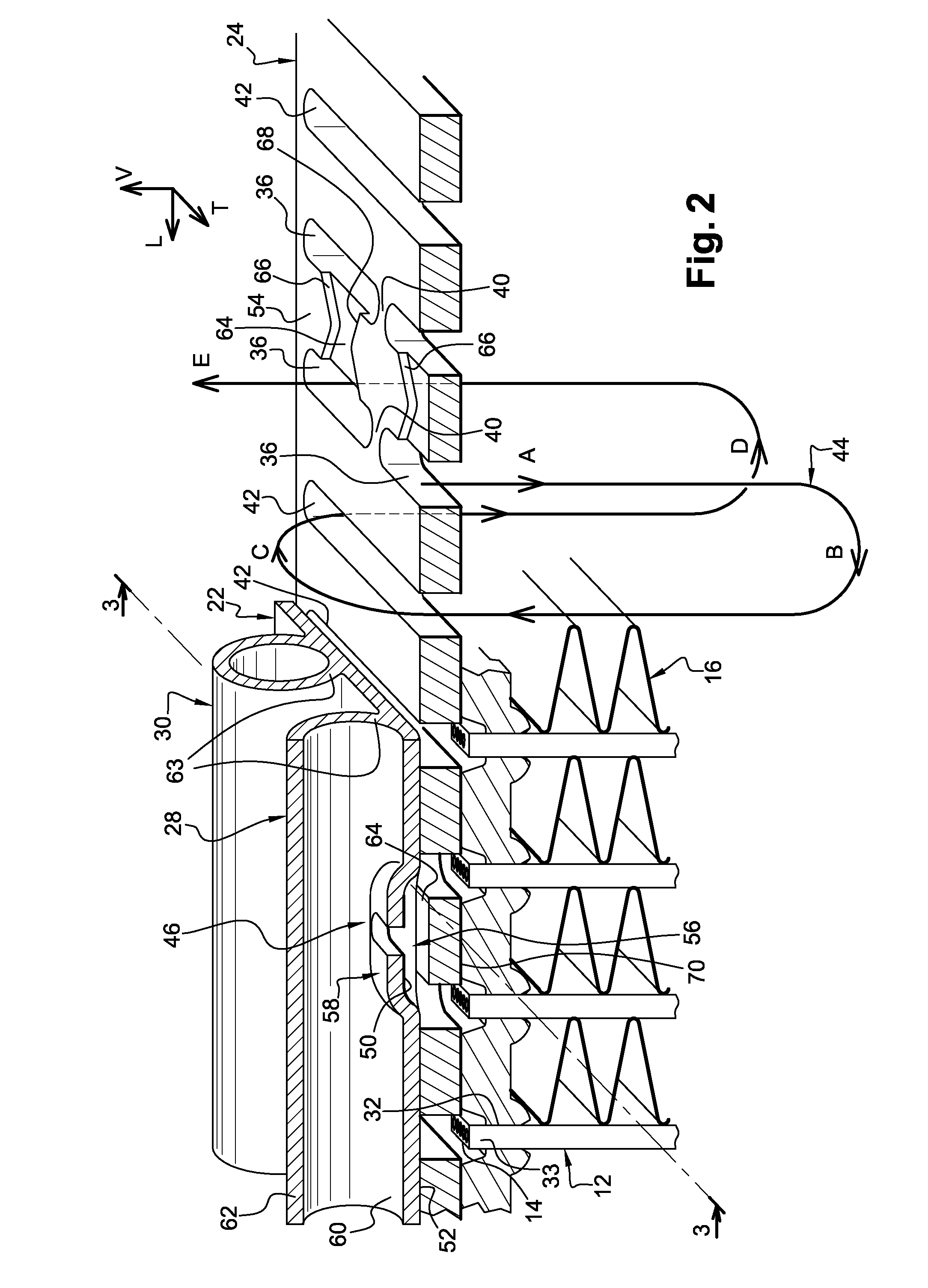
[0030]FIGS. 1 and 2 show an evaporator 10 for a motor vehicle air-conditioning system which is operated with CO2 as refrigerant according to a preferred embodiment of the present invention. This evaporator 10 is designed as a two rows flat-tube evaporator and has a multiplicity of flat tubes 12 arranged along two longitudinal rows R1, R2, a front row R1 on the front side of the evaporator 10 and a rear row R2 on the rear side of the evaporator 10. These flat tubes 12 can be designed as extruded multi-channel flat tubes, which have a multiplicity of flow passages 14. All the flat tubes 12 have the same length along a vertical axis V and the same depth D along a transverse axis T.

[0031]In the following description, for the purpose of better understanding, we will use an orientation along the vertical axis V, the longitudinal axis L, and the transverse axis T, as can be seen on FIG. 1.

[0032]Preferably, the flat tubes 12 are multiport extruded flat tubes.

[0033]Between the individual fla...


PUM

PropertyMeasurementUnit
Shapeaaaaaaaaaa

Abstract

A heat exchanger, in particular for a motor vehicle, comprises a collector box and at least one longitudinal row of multi-channel flat tubes through which a first fluid can flow. The collector box is made up of stacked plates including:
    • a header plate with at least one row of mounting slots receiving an end portion of each tube,
    • a distribution plate comprising at least one row of distribution slots,
    • a cover plate comprising at least one row of collecting apertures which connect at least some of the distribution slots to a manifold, at least one collecting aperture being arranged between two adjacent distribution slots.
Said collecting aperture is arranged in a main recess provided in the bottom face of the cover plate.

Description

TECHNICAL FIELD[0001]The present invention relates generally to heat exchanger for motor vehicles.BACKGROUND OF THE INVENTION[0002]The present invention relates more particularly to a heat exchanger such as an evaporator, comprising a collector box and at least one longitudinal row of multi-channel flat tube portions through which a first fluid such as a refrigerant fluid can flow and around which a second fluid such as air can flow, said tube portions being flat along a transverse direction and being connected to the bottom face of the collector box, wherein the collector box is made up of stacked plates including:[0003]a distribution plate comprising at least one row of distribution slots which distribute the first fluid in the collector box,[0004]a cover plate comprising at least one row of collecting apertures which connect at least some of the distribution slots to a manifold, at least one collecting aperture being a collecting aperture arranged between two adjacent distributio...

Claims


Application Information

Patent Timeline
IPC IPC(8): F28F9/02B21D53/02
CPCF25B39/028F25B41/00Y10T29/4935F28D1/05391F28F9/0278F28D1/0476
Inventor BIVER, PHILIPPEDAMOTTE, HERVE
Owner DELPHI TECH INC
Why Eureka
Try Eureka