Temperature control apparatus of working machine

Inactive Publication Date: 2010-12-23
DMG MORI SEIKI CO LTD
View PDF32 Cites 7 Cited by
  • Summary
  • Abstract
  • Description
  • Claims
  • Application Information

AI Technical Summary

Benefits of technology

[0018]The temperature control apparatus of a working machine according to the present invention including ventilating means for replacing internal air in the working area with external air surrounding the working machine between a working area inside the working machine and an exterior of the working machine comprises a ventilating means control unit that compares the temperature in the working area, which is detected with the working area temperature sensor, the external temperature surrounding

Problems solved by technology

Consequently, thermal displacement caused by the temperature difference between the temperature in the room in which the machine tool is installed and the temperature in the working area will occur in the respective components of the machine tool, which is undesirable in terms of w

Method used


Image

  • Temperature control apparatus of working machine
  • Temperature control apparatus of working machine
  • Temperature control apparatus of working machine

Examples


Example

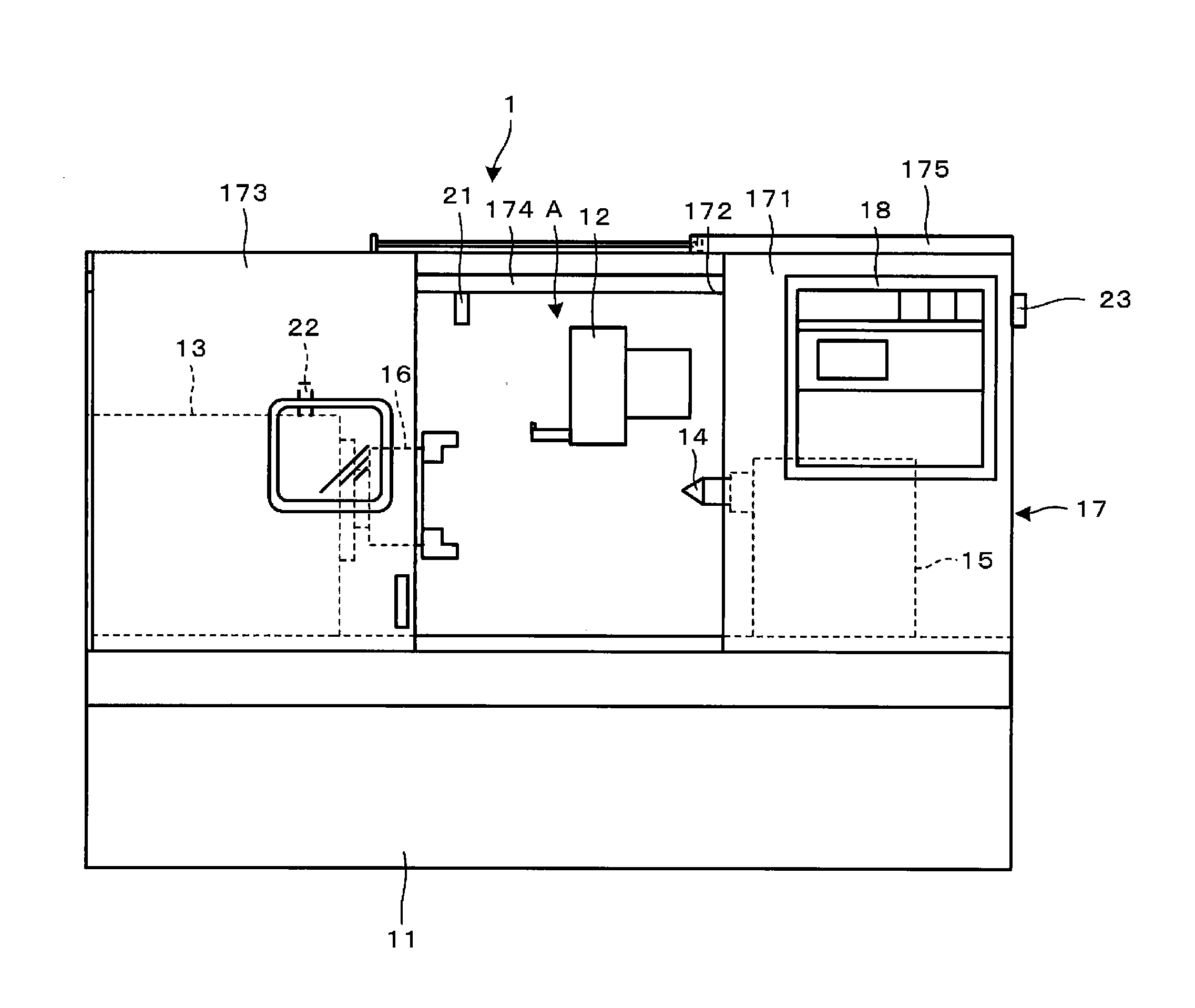
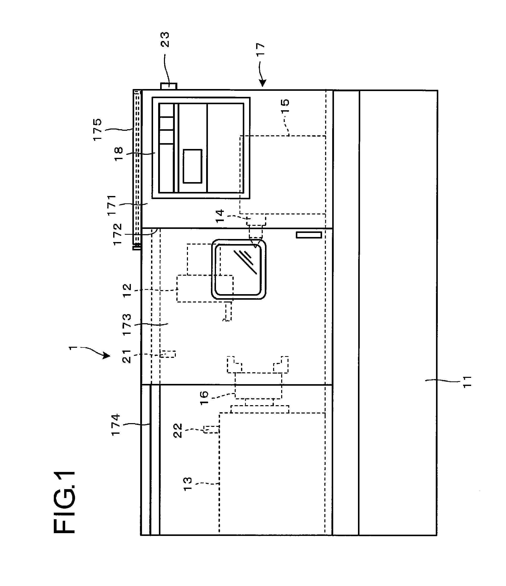
[0023]Embodiments of this invention will be explained with reference to the drawings below. FIG. 1 is a front view showing a general composition of a numerically controlled lathe provided with the temperature control apparatus of a working machine according to an embodiment of the present invention and showing a state where the cover for covering the opening for working is closed. FIG. 2 is a front view of the numerically controlled lathe of FIG. 1 showing a state where a cover for covering the opening for working is open.

[0024]A numerically controlled lathe 1 shown in FIG. 1 and FIG. 2 is composed of a tool rest 12 that is disposed movably in the X axis and Z axis directions on a bed 11, a headstock 13 that is fixed on the bed 11 and a tailstock 15 including a tailstock spindle 14 that is disposed movably in the Z axis direction on the bed 11.

[0025]A chuck 16 is mounted on the tip of a work piece spindle (not shown) of the headstock 13 and the work piece (not shown) is gripped by t...


PUM


Abstract

Provided is a temperature control apparatus of a working machine that is inexpensive, energy-saving and capable of eliminating the temperature difference between a temperature in a room in which the working machine is installed and a temperature of a working area.
Whether an average value T5 is higher or lower than both a target temperature T1 in the working area and an air temperature T2 in the room is checked and, if the result is YES, the routine proceeds to step S8 for driving a cylinder 175 to open a cover 173 and open a opening for working 172. Then, internal air in a working area A is replaced with external air surrounding a numerically controlled lathe 1 and the temperature in the working area approaches the air temperature T2 in the room. If the result is NO, the cylinder 175 is driven to close the cover 173 and close the opening for working 172. Then, replacement of the internal air in the working area A with the external air surrounding the numerically controlled lathe 1 is ended and the operation of the temperature control apparatus is ended.

Description

FIELD OF THE INVENTION[0001]The present invention relates to a temperature control apparatus of a working machine and in particular relates to a temperature control apparatus of a machine tool such as a numerically controlled lathe or a machining center.BACKGROUND OF THE INVENTION[0002]With a machine tool such as a numerically controlled lathe or a machining center, a spindle is rotated to move a tool rest, a spindle head and the like in order to perform cutting work on a work piece. Thus, the temperature of the respective components of the machine tool will rise due to the heat generation in the motor or rotating portion and the heat generation caused by the contact of the tool and the work piece.[0003]Even in the following morning after the operation of the machine tool is ended, there are cases where the heat generated in the previous day remains in the respective components of the machine tool. Consequently, thermal displacement caused by the temperature difference between the t...

Claims


Application Information

Patent Timeline
IPC IPC(8): G05D23/00F28F13/12
CPCB23Q11/148G05D23/2039G05D23/1931
Inventor SUGIMOTO, YOSHIAKIHOSHI, TAKASHIYOSHIOKA, KIYOSHIYAMADA, SOICHIRO
Owner DMG MORI SEIKI CO LTD
Why Eureka
Try Eureka