White light emitting apparatus and line illuminator using the same in image reading apparatus

a technology of light emitting apparatus and image reading apparatus, which is applied in the direction of lighting and heating apparatus, process and machine control, instruments, etc., can solve the problem of comparatively high total cost of obtaining white leds, and achieve the effect of reducing the cost of producing white leds and reducing the number of products

Inactive Publication Date: 2010-12-23
CANON COMPONENTS INC
View PDF14 Cites 130 Cited by
  • Summary
  • Abstract
  • Description
  • Claims
  • Application Information

AI Technical Summary

Benefits of technology

[0022]According to the white light emitting apparatus of the present invention, by using a combination of white LEDs that emit light colors whose chromaticity deviates from a predetermined white region among ranked white regions that are being provided as products, it is possible to utilize white LEDs that have a wide range of chromaticities. More specifically, the white light emitting apparatus of the present invention lowers the cost of producing white LEDs by reducing the number of products that have heretofore been wasted due to hue deviations that are inherent to white LEDs that include a blue LED chip and a YAG phosphor.
[0023]Further, according to the white light emitting apparatus of the present invention, it is possible to emit light of a predetermined white region that is a target without employing a complicated configuration that has been used in the conventional technology such as newly adding a LED chip that emits light of a different wavelength or a different kind of fluorescent substance, or changing the phosphor composition in order to compensate for chromaticity variations that are a drawback of white LEDs.
[0024]Further, for example, by using the white light emitting apparatus according to the present invention as a light source of a line illuminator, a bright line illuminator that illuminates with a prescribed white chromaticity can be economically produced.

Problems solved by technology

However, when a light source is constructed using only white LEDs that have a specific ranking, white LEDs with a different ranking are wasted, and there is thus the problem that the total cost for obtaining the white LEDs is comparatively high.

Method used


Image

  • White light emitting apparatus and line illuminator using the same in image reading apparatus
  • White light emitting apparatus and line illuminator using the same in image reading apparatus
  • White light emitting apparatus and line illuminator using the same in image reading apparatus

Examples


first embodiment

[0069]A white light emitting apparatus used in an image reading apparatus according to the First Embodiment is provided with two white LEDs. Each of the white LEDs includes a blue LED chip, and a phosphor layer which is excited by a radiation light emitted by the blue LED chip and emits a yellow light. Yellow is a complementary color of blue. In the First Embodiment, a white light emitting apparatus 20 having two white LEDs will be explained with reference to FIGS. 1 to 4, and FIG. 9.

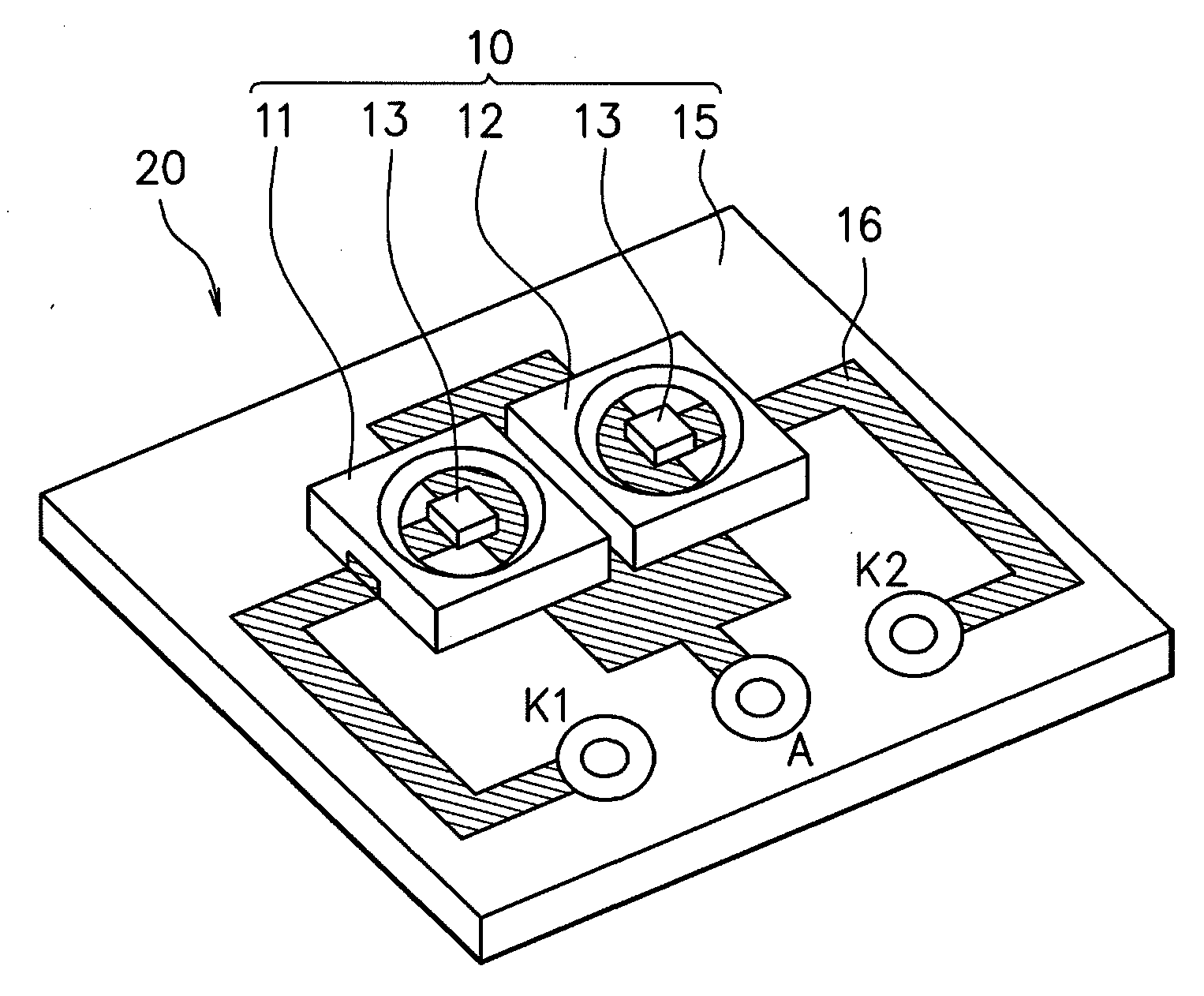
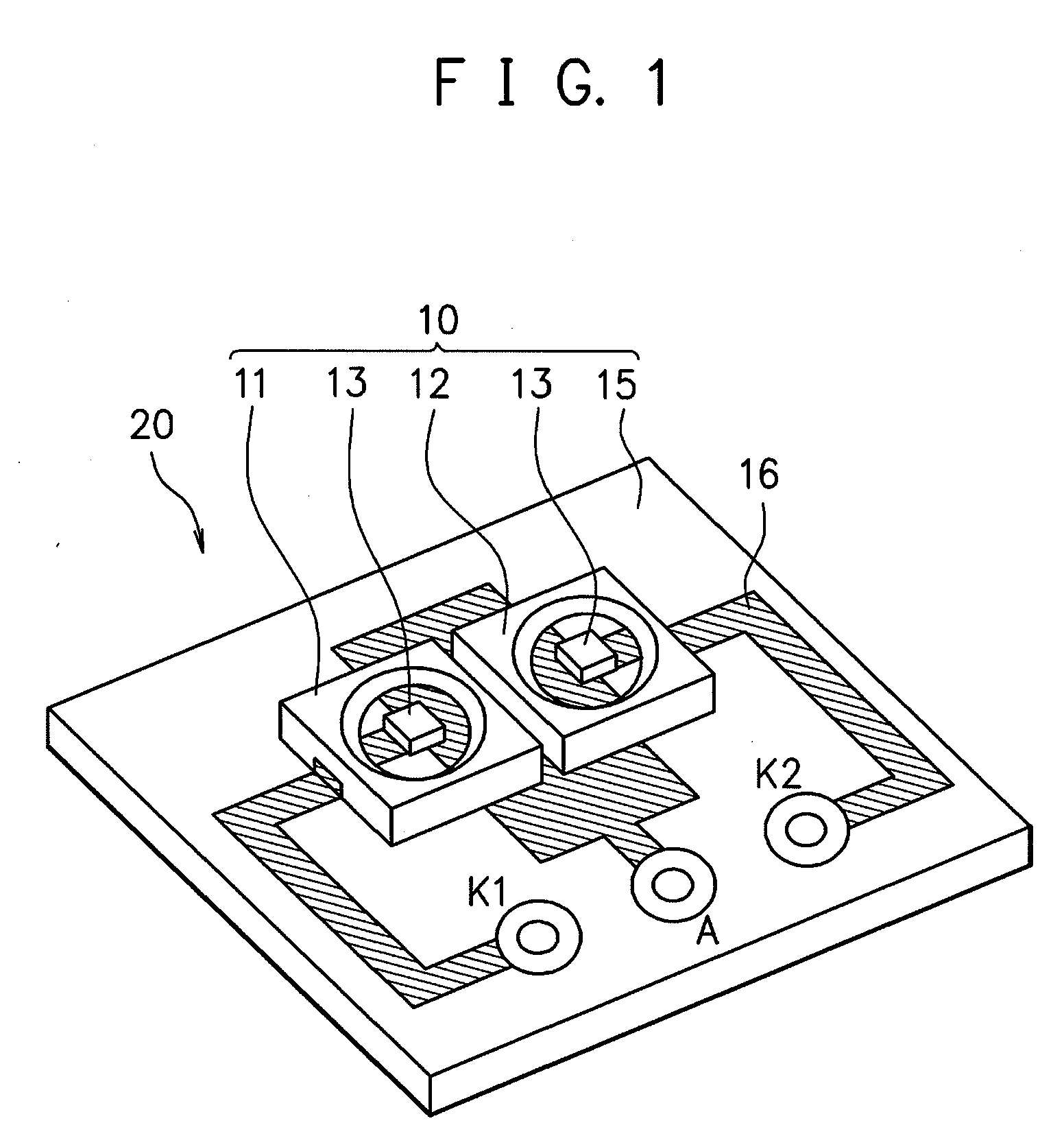
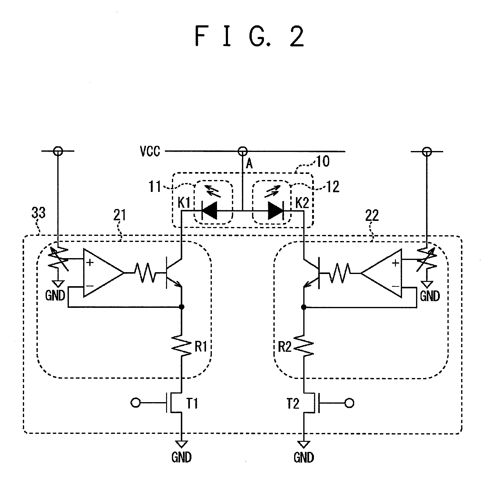
[0070]The white light emitting apparatus 20 of the present embodiment includes a light source section 10 and a current regulation section 33. FIG. 1 illustrates the light source section 10 of the white light emitting apparatus 20. The light source section 10 includes a first white LED 11 for emitting a white light of A region which deviates to the blue side from the predetermined white region (B region) among the aforementioned ranked white region (A region+B region+C region) and a second white LED 12 f...

second embodiment

[0090]The Second Embodiment relates to PWM control of drive currents that effectively drives the two white LEDs used in the white light emitting apparatus of the First Embodiment to further increase the luminosity of the white light emitting apparatus that mixes the emitted light colors of the two white LEDs. The present embodiment also relates to a white light emitting apparatus that enables selection and use of white LEDs in which the chromaticities of emitted lights are distributed over a wide region by means of PWM control. The emitted light colors of the first and second white LEDs of the Second Embodiment are described using chromaticities inside the A region and C region, respectively, similarly to the First Embodiment.

[0091]First, current control that adjusts the chromaticity of a white light emitting apparatus that includes the two white LEDs is described in a case in which, on the CIE chromaticity diagram, there is a difference in the distance to the target point PD0 of th...

third embodiment

[0098]The Third Embodiment relates to a line illuminator 50 that uses the white light emitting apparatus 20 of the First Embodiment. The line illuminator 50 is described in detail below with reference to FIGS. 12 to 15.

[0099]The line illuminator 50 of the present embodiment is used to illuminate an original copy surface such as a paper surface in an image reading apparatus, for example. The line illuminator 50 is, as illustrated in FIG. 12, provided with a bar-shaped light guide member 51 that is formed of a clear material and has a light incident surface 54 at one end thereof, and a light source section 10 disposed toward the light incident surface 54. The light source section 10 is connected with the current regulation section 33 via a terminal lead wire 62 as in the case of the First Embodiment (not illustrated in FIG. 12). The light guide member 51 is provided with a light guiding section 52 for guiding an incident light from the light incident surface 54 in the longitudinal dir...


PUM


Abstract

A white light emitting apparatus includes a light source section in which a first white LED that emits white light whose chromaticity deviates to a blue side from a predetermined white region of a CIE chromaticity diagram and a second white LED that emits white light whose chromaticity deviates to a yellow side from the predetermined white region are adjacently disposed so as to emit light with optical axes in substantially the same direction, and a current regulator that independently drives the blue LED chip in the first and second white LEDs, respectively. A color mixture of lights emitted from the first and second white LEDs is adjusted to a chromaticity of the predetermined white region using the current regulator.

Description

CROSS-REFERENCE TO RELATED APPLICATIONS[0001]This is a continuation-in-part application of International Application No. PCT / JP2008 / 063839, with an international filing date of Aug. 1, 2008, which designating the United States of America, the entire contents of which are incorporated herein by reference.[0002]This application is based upon and claims the benefit of priority of the prior Japanese Patent Application No. 2008-031470, filed on Feb. 13, 2008, the Japanese Patent Application No. 2009-186880, filed on Aug. 11, 2009, and the Japanese Patent Application No. 2010-049662, filed on Mar. 5, 2010, the entire contents of which are incorporated herein by reference.TECHNICAL FIELD[0003]The present invention relates to a white light emitting apparatus and a line illuminator that uses the white light emitting apparatus in an image reading apparatus. In particular, the present invention relates to a white light emitting apparatus on which a white LED is mounted and a line illuminator t...

Claims


Application Information

Patent Timeline
Patent Type & Authority Applications(United States)
IPC IPC(8): H05B37/02F21V8/00H01L33/50
CPCH01L25/0753H01L33/50H05B33/0818H05B33/086Y02B20/347H01L2224/48247H01L2224/48091H01L2924/00H01L2224/48257H05B45/20H01L2924/00014Y02B20/30
Inventor KAIHOTSU, TAKAHIROASAI, SHOZO
Owner CANON COMPONENTS INC
Why Eureka
Try Eureka