Antenna elements, arrays and base stations including mast-mounted antenna arrays

an array and antenna technology, applied in the direction of antenna details, polarised antenna unit combinations, antennas, etc., can solve the problems of heavy parts and high cost, and achieve the effect of automatic and accurate placement of antenna elements

Inactive Publication Date: 2010-12-23
LUCENT TECH INC
View PDF10 Cites 13 Cited by
  • Summary
  • Abstract
  • Description
  • Claims
  • Application Information

AI Technical Summary

Benefits of technology

[0014]The antenna element may be surface mounted on a ground plane. Surface mount technology allows automated and accurate placement of an antenna element, and is particularly advantageous where a large number of antenna elements are used as an array of an antenna arrangement, for example. The support provided by the circular surround of an antenna element makes the design particularly mechanically stable, and thus suitable for such assembly techniques, and this is enhanced where the parts of the element are included as a single integral component. The antenna element, or elements, may be mounted on a ground plane defined by a metallization layer on a printed circuit board (PCB). The printed circuit board may also carry circuitry, for example, a balun connected to the antenna element, and other components on the opposite side to that one which the antenna element is mounted, or in layers of the PCB where the PCB is a multilayer board. A balun is a balanced-to-unbalanced converter, or 180° hybrid, and is used to balance the feeds.

Problems solved by technology

The frequency selectivity specifications for duplexer filters are very demanding, leading to them being expensive, heavy parts.

Method used


Image

  • Antenna elements, arrays and base stations including mast-mounted antenna arrays
  • Antenna elements, arrays and base stations including mast-mounted antenna arrays
  • Antenna elements, arrays and base stations including mast-mounted antenna arrays

Examples


Embodiment Construction

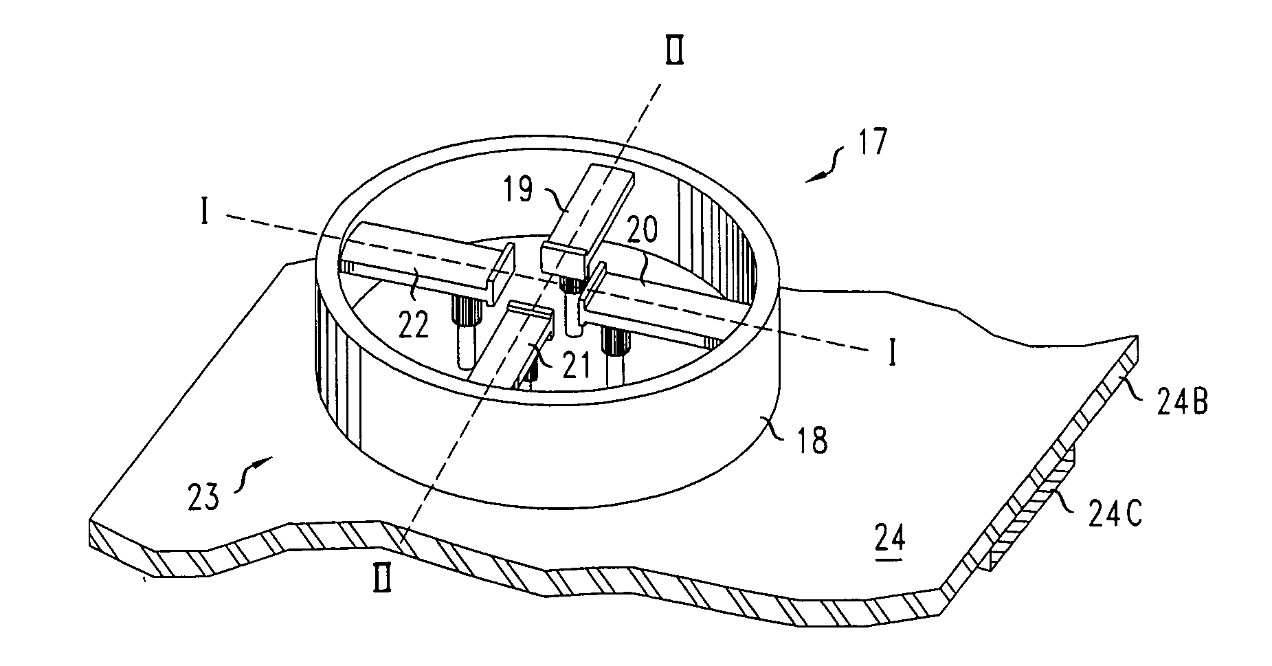
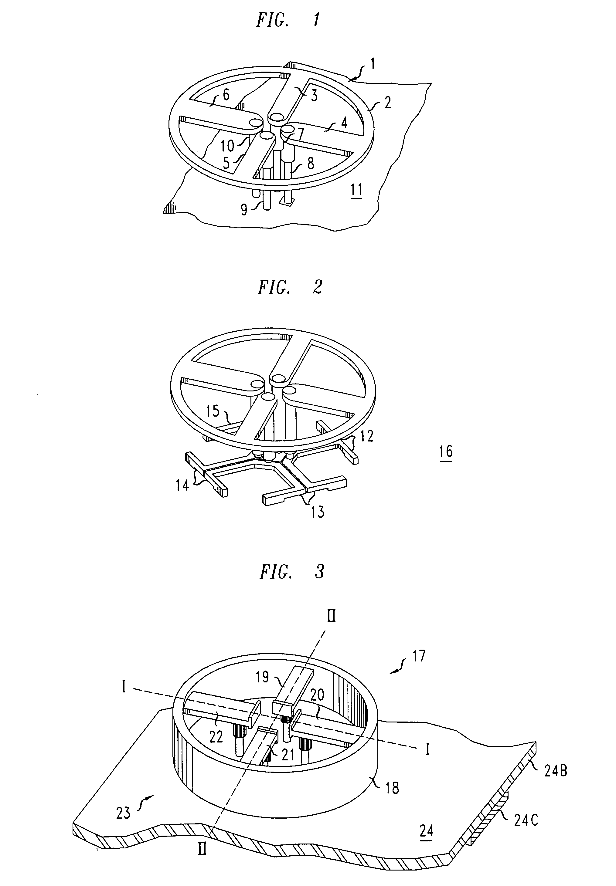
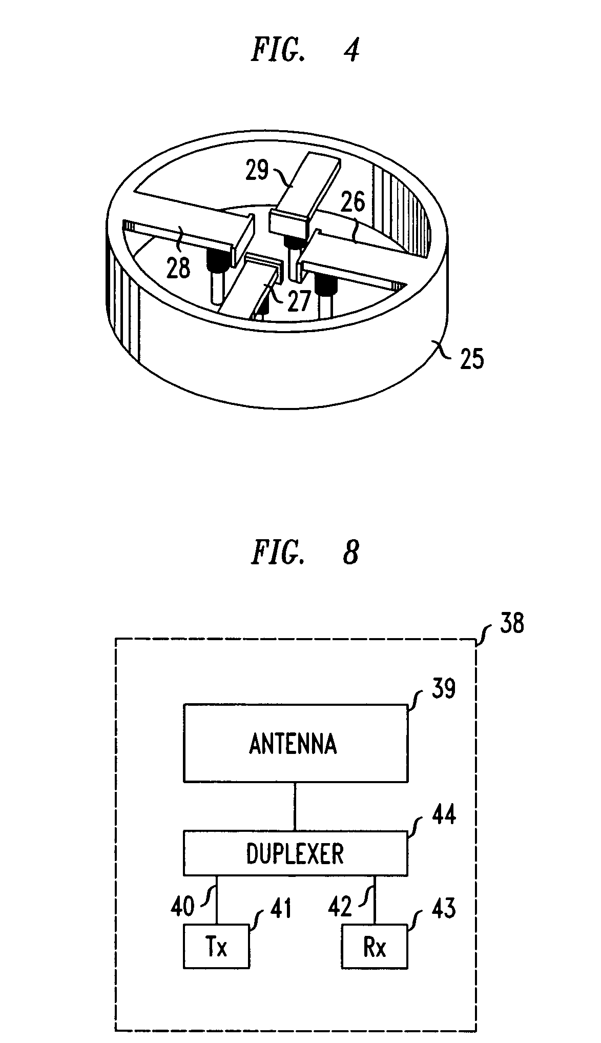
[0026]With reference to FIG. 1, an antenna element 1 comprises a circular cross-section surround 2 and four orthogonal feed sections 3, 4, 5 and 6, which are radially extensive inwardly of the support 2 and electrically connected to it. Support posts 7, 8, 9 and 10 are connected to the free ends of the feed sections 3, 4, 5, and 6. The surround 2, feed sections 3, 4, 5 and 6, and support posts 7, 8, 9 and 10 are all part of a single integral component, which in this embodiment is of injection molded metallized plastic. The antenna element 1 is located over a conductive ground plane 11. The support posts 7, 8, 9 and 10, are insulated from the ground plane 11 and, in addition to supporting the antenna element and fixing it in position, also provide signal paths for transmitted and received signals radiated and received by the antenna element 1. This is a broadband structure and based on the crossed dipole principle. It shows dual orthogonal polarization, that is, horizontal plus verti...


PUM


Abstract

An antenna element 1 comprises a surround 2 of substantially circular cross-section and a plurality of feed sections 3, 4, 5 and 6 electrically connected to the surround 2. The feed sections are extensive substantially radially and inwardly from it. The surround may be cylindrical in other embodiments. The antenna element may be fabricated as single, integral component, for example, from metallized plastic using injection molding. The antenna element may be arranged to be frequency selective for transmit and receive, which is particularly applicable where it is incorporated in an antenna array used in a base station of a wireless communications system.

Description

FIELD OF THE INVENTION[0001]The present invention relates to antenna elements, to antenna arrangements including an array of antenna elements and to wireless communications base stations including mast-mounted antenna arrays.BACKGROUND OF THE INVENTION[0002]Antennas used in wireless communications base stations are generally mounted on a mast to achieve maximum coverage. If antennas are used for both transmission and reception of signals, some protection must be provided to ensure that receiving components are not damaged by transmitted signals of relatively high power. Alternatively, separate antennas can be used for transmission and reception, but, depending on their physical separation, a fraction of the transmitted power will still reach the receive path. Therefore, protection of the sensitive receive electronics remains necessary.[0003]At the radio-frequency (RF) front-end of full-duplex, frequency division duplex (FDD) communication systems, high power transmit signals are pre...

Claims


Application Information

Patent Timeline
Patent Type & Authority Applications(United States)
IPC IPC(8): H01Q1/12H01Q1/24H01Q21/00
CPCH01Q1/246H01Q21/24H01Q21/06H01Q9/265
Inventor HESSELBARTH, JAN
Owner LUCENT TECH INC
Why Eureka
Try Eureka