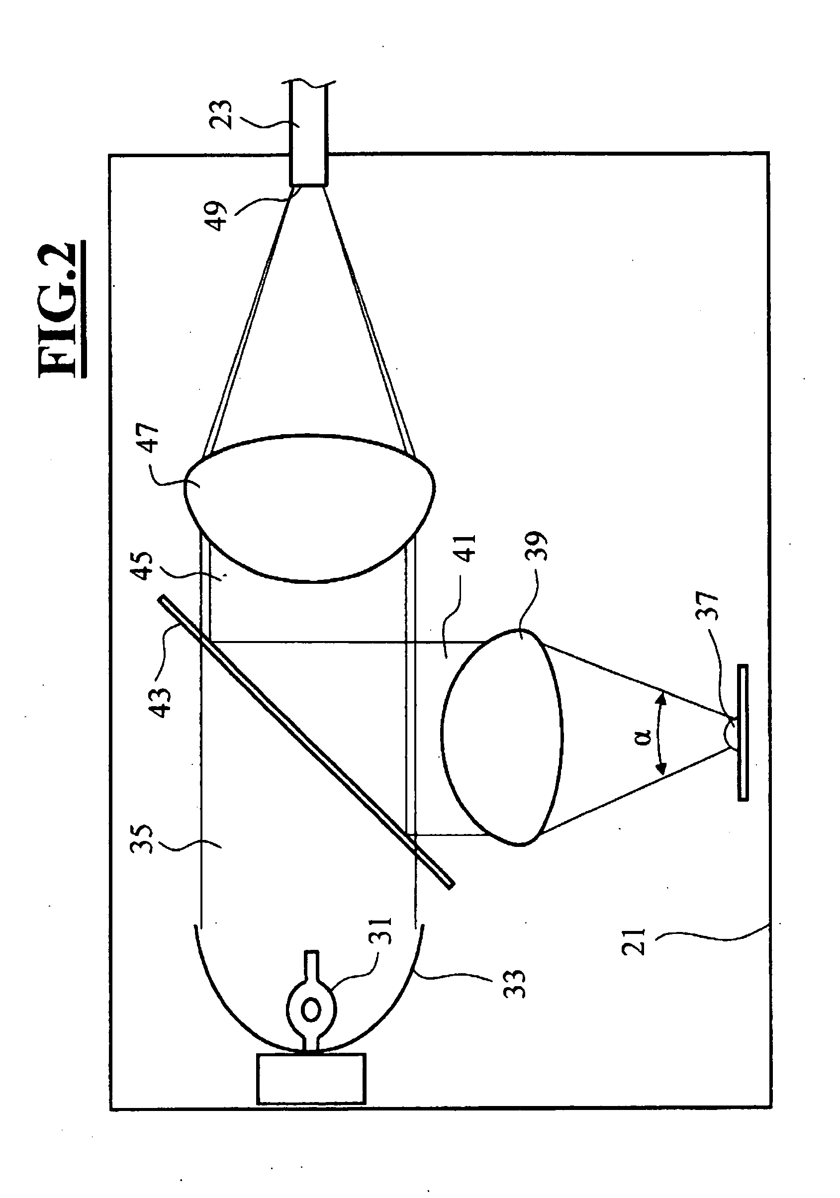
[0010]An illuminating system of the invention for an optical viewing apparatus, which is operable in a fluorescence mode, includes at least one
broadband light source for illuminating a viewed object, for example, a
halogen lamp, a
gas discharge lamp, a
metal-
halide lamp, a broadband
semiconductor light source, a broadband organic light source, et cetera. In addition, the illuminating system includes at least one narrowband light source for exciting fluorescence in the viewed object and / or for background illumination in the fluorescence mode. The narrowband light source can be especially a
laser or a
luminescence emitter such as a
light emitting diode or an organic
light emitting diode, et cetera. Furthermore, the illuminating system of the invention includes a light conductor having a light source end inlet end and a object end outlet end as well as a superposer for superposing the light of the narrowband light source with the light of the
broadband light source. The superposer can especially include at least one dichroic mirror and, for example, be configured as a
prism having at least one
prism surface provided with a dichroic mirror. The superposer is mounted at the inlet end of the light conductor or, ahead of the inlet end of the conductor at the light source side. When the superposer is configured as a
prism, it affords the
advantage that light from more than two light sources can be superposed by the same superposer.
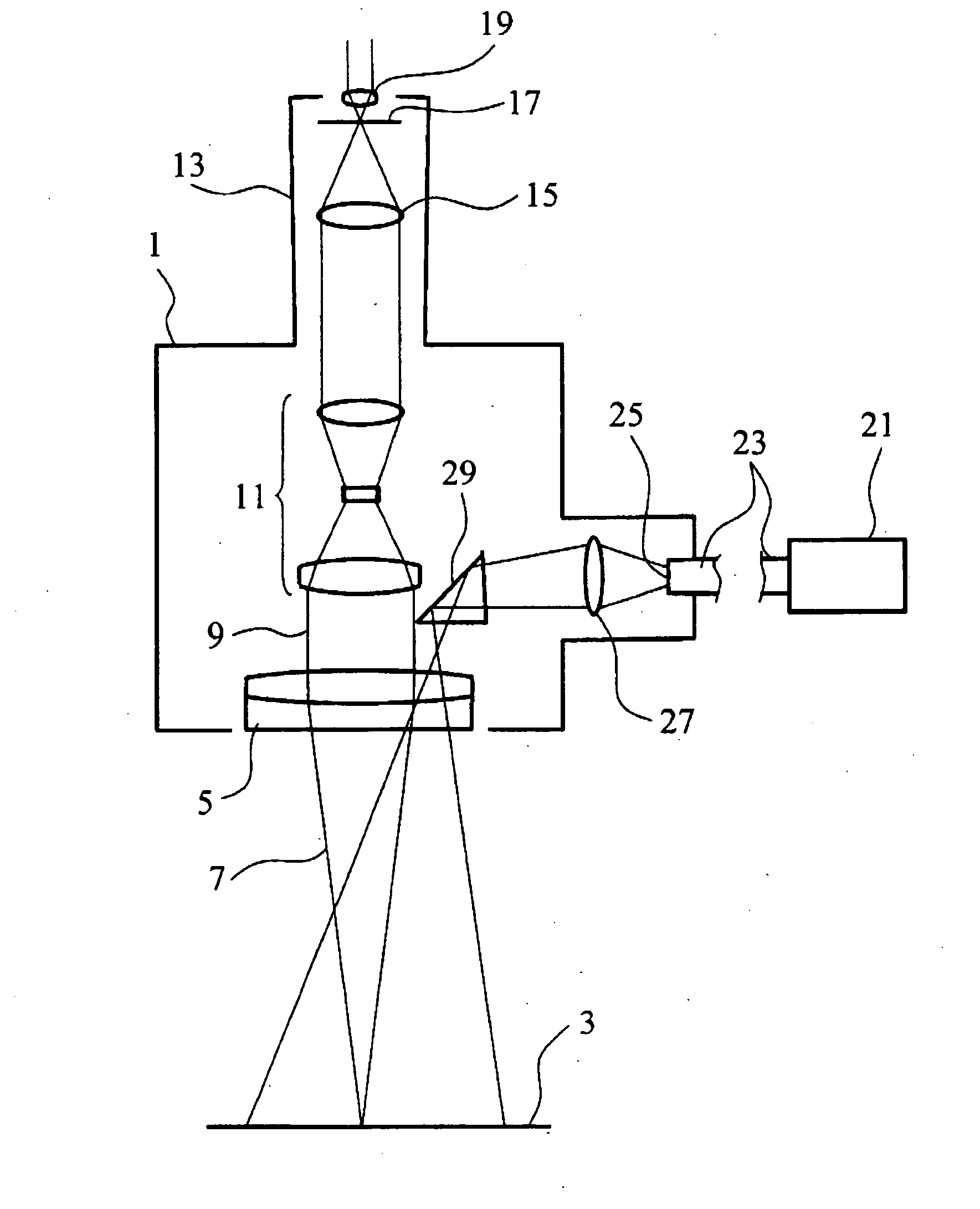
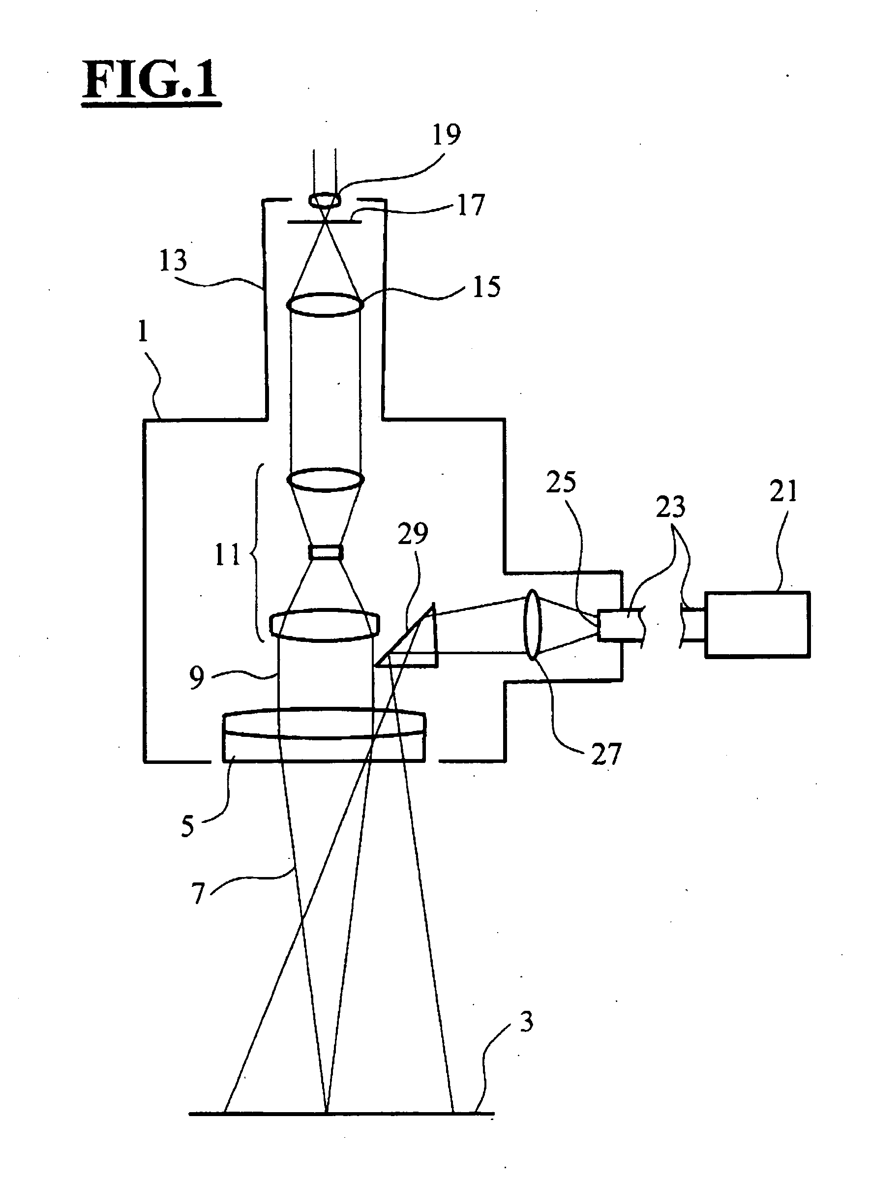
[0011]In the illuminating system of the invention, the
white light as well as the excitation light for the fluorescence are conducted in common through the light conductor onto the object. In a
surgical microscope, a light source of this kind can replace a conventional illuminating system with a light conductor through which the light is conducted to the optical viewing apparatus without changes in the construction of the optical viewing apparatus being necessary such as for
coupling the excitation
radiation into the viewing beam path. The illuminating system of the invention is therefore suitable in an advantageous manner also for
retrofitting or refitting existing optical viewing apparatus to fluorescence apparatus.
[0012]In a further advantageous embodiment of the illuminating system of the invention, the illuminating system includes a switching unit for individually switching the narrowband light source on and off independently of the switched state of the
broadband light source. In this configuration, the narrowband light source can be switched on and off independently of the broadband light source. For this reason, for example, the fluorescence can be excited with the broadband light source and the narrowband light source can be additionally applied as needed for exciting the fluorescence in order to increase the intensity of the excitation
radiation relative to the sole use of the broadband light source. Especially for weak fluorescence, the generation of fluorescence radiation can thereby be brought about with adequate intensity. Even for deep surgical channels, it can be advantageous to increase the excitation intensity relative to the sole use of the broadband light source for exciting the fluorescence by switching in the narrowband light source. If, in addition, the broadband light can be switched on and off independently of the narrowband light source, then the narrowband light source can also be used by itself for fluorescence excitation, that is, without the broadband light source.
[0013]When the illuminating system includes an adjusting device for individually adjusting the intensity of the broadband light source independently of the intensity of the narrowband light source, then, during the fluorescence excitation, the broadband light source as a background illumination can be held to a low intensity level sufficient for the conventional viewing of the viewed object, that is, the broadband light source need not be operated at maximum power in order to make sufficient excitation radiation available. In this way, the stress on the patient because of the high white
light intensity can be avoided during fluorescence excitation.
[0015]In a further embodiment of the invention, the illuminating source includes at least two narrowband light sources whereby a higher intensity of the excitation radiation for the fluorescence can be achieved. If, in addition, a switching arrangement is provided for the individual switching on and off of the at least two narrowband light sources independently of each other, the intensity of the excitation radiation can be increased by switching in at least one of the narrowband light sources which is especially advantageous when there is weak fluorescence or deep surgical channels. If an adjusting device is present for individually adjusting the intensity of the at least two narrowband light sources independently of each other, the intensity, with which the viewed object is illuminated for excitation of the fluorescence radiation, can be continuously adjusted over a wide range especially when the two narrowband light sources can, in addition, also be switched on and off separately.
[0016]It is also possible to provide at least two narrowband light sources which emit at different wavelengths. In this way, the excitation of different fluorescent molecules is possible with the same illuminating system.

