Pantograph damage and wear monitoring system

a technology of wear monitoring and pantograph, which is applied in the field of automatic pantograph damage and wear monitoring system, can solve the problems of pantograph damage, dewirement and/or damage, and easy crack damage, and achieve the effects of excessive noise, long exposure time, and high gain valu

Inactive Publication Date: 2010-12-23
QUEENSLAND RAIL LIMITED
View PDF11 Cites 44 Cited by
  • Summary
  • Abstract
  • Description
  • Claims
  • Application Information

AI Technical Summary

Benefits of technology

[0046]It will be appreciated that when a locomotive is detected at the monitoring site and the at least one image capture device detects that there is insufficient light to capture a suitable image of a pantograph the program automatically activates the backing screen lighting. Alternatively, the backing screen can be permanently illuminated. Preferably, the backing screen is illuminated uniformly. It will also be appreciated by one of skill in the art that this is necessary to ensure consistency between captured images. An overly long

Problems solved by technology

A major problem with the carbon blocks is that they are susceptible to crack damage.
Misalignment of electrical sectioning equipment, excessive arcing and constant friction can all cause significant damage to the carbon block.
If not detected and repaired, such damage can cause dewirement and/or damage to the pantograph generally and therefore render a train inoperable.
The labour costs and operational down time associated with such an inspection process are clearly undesirable.
If sufficient damage is sustained by the pantograph, the tube ruptures causing a drop in system pressure.
Optical signals are trans

Method used


Image

  • Pantograph damage and wear monitoring system
  • Pantograph damage and wear monitoring system
  • Pantograph damage and wear monitoring system

Examples


Embodiment Construction

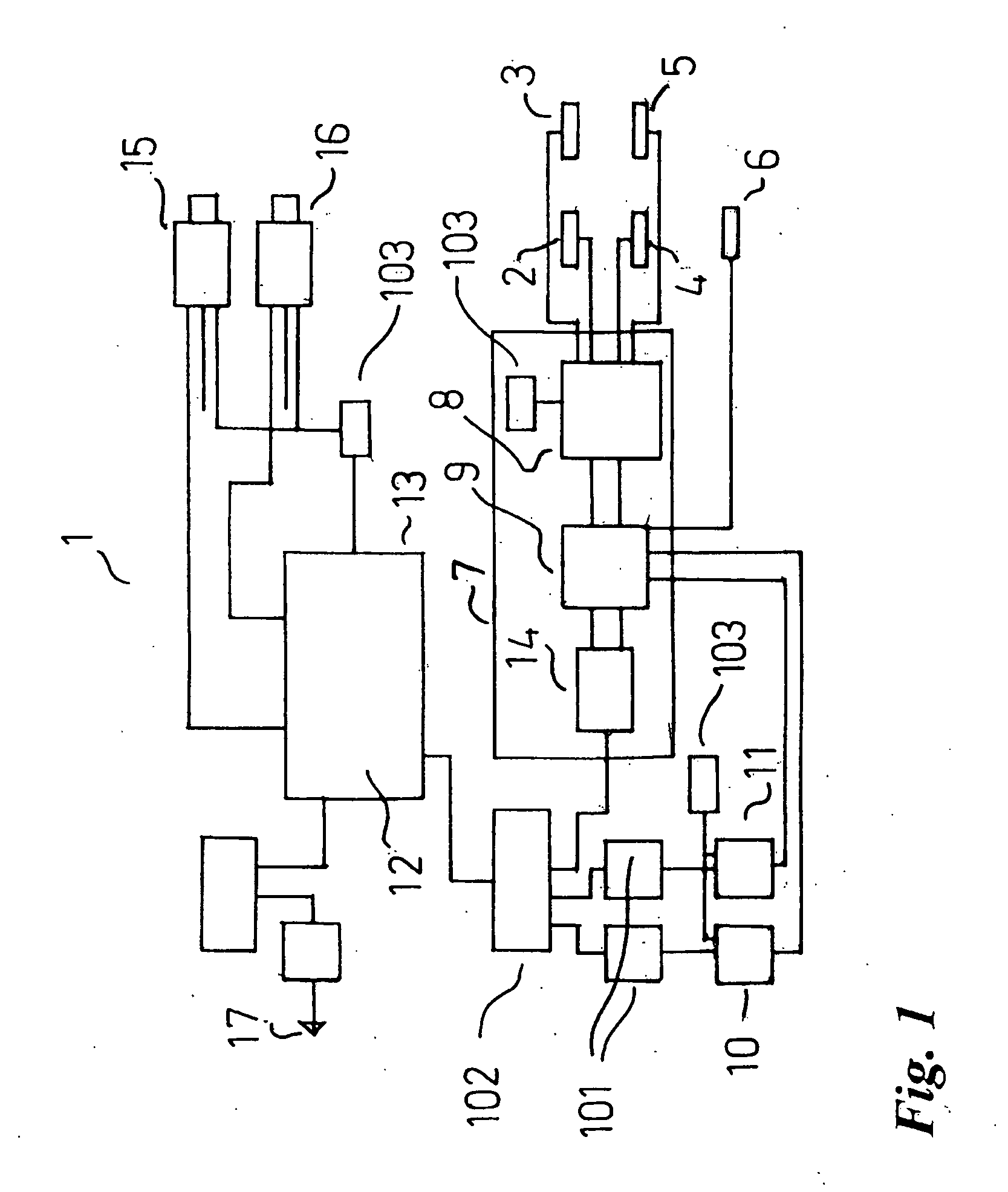
[0085]With reference to FIG. 1, there is shown a monitoring system 1 installed at a monitoring site comprising: top position sensors 2 and 3; side position sensors 4 and 5; and locomotive sensor 6. Signals emanating from the sensors, when a pantograph is present at the monitoring station, are received by sensor interface 7. Sensor interface 7 comprises a sensor signal conditioner 8 and interface circuit 9. On simultaneous receipt of a signal indicating the presence of a locomotive at the monitoring station and a signal indicating the presence of a pantograph at the monitoring station, interface circuit 9 splits the signals into two streams. The first stream activates AVI tag readers 10 and 11, which capture the serial number of the locomotive at the monitoring site. Data received from tag readers 10 and 11 is converted to USB format via converters 101 (e.g. RS 422 to USB) and proceeds via USB hub 102 to the station management system 12, running on computer 13, where it is stored. Th...


PUM


Abstract

A system for evaluating the condition of a pantograph, the system comprising: a track-side pantograph monitoring station that captures one or more images of a pantograph, while a locomotive comprising the pantograph is in normal service; a station management system that analyses one or more images captured at the monitoring site and determines the condition of the pantograph; and a user interface that controls the system and presents the results of the analysis to the user. A user may control the track-side monitoring station and station management system remotely.

Description

TECHNICAL FIELD[0001]The invention described herein relates to locomotive pantographs. In particular, the invention is directed to an automated pantograph damage and wear monitoring system, although the scope of the invention is not necessarily limited thereto.BACKGROUND ART[0002]Most electrified trains utilise pantographs to transmit electricity from an overhead wire to the train. Pantographs of modern high speed, electrified trains comprise carbon current collectors. These carbon current collectors typically comprise a carbon block support and a carbon block that contacts the wire. The carbon block functions inter alia to minimise the wear on the overhead wire. A major problem with the carbon blocks is that they are susceptible to crack damage. Misalignment of electrical sectioning equipment, excessive arcing and constant friction can all cause significant damage to the carbon block. If not detected and repaired, such damage can cause dewirement and / or damage to the pantograph gen...

Claims


Application Information

Patent Timeline
IPC IPC(8): G06K9/00H04N7/18
CPCB60L5/24B60L2200/26B60M1/28G06T7/0004
Inventor WESCHE, DARRYLWATKINS, TIMOTHY JOHNHAMEY, LEONARD GEORGE CHARDBORN
Owner QUEENSLAND RAIL LIMITED
Why Eureka
Try Eureka