Tapered roller bearing

a roller bearing and tapered technology, applied in the direction of gearing details, mechanical equipment, gearing surfaces, etc., can solve the problems of inability to expect long-term fretting suppression effect, favorable, contact surface wear, etc., to prevent occurrence of fretting, and suppress occurrence of fretting

Active Publication Date: 2010-12-23
NTN CORP
View PDF8 Cites 7 Cited by
  • Summary
  • Abstract
  • Description
  • Claims
  • Application Information

AI Technical Summary

Benefits of technology

[0025]In the first, third, and fifth tapered roller bearings of the present invention, contact surface pressure between the tapered roller and the raceway surfaces can be reduced to under 2200 MPa. Therefore, the occurrence of fretting can be suppressed without reducing fatigue life.
[0026]In particular, as a result of MoS2 processing being performed on the surface of the tapered roller, as in the second, fourth, and sixth tapered roller bearings, even when the contact surface pressure between the tapered roller and the raceway surfaces does not fall below 2200 MPa, the occurrence of fretting can be prevented with a surface pressure near 2200 MPA. Therefore, as a result of MoS2 processing being performed on the surface of the tapered roller, the occurrence of fretting can be prevented even when Cor / Cr≧1.3, α≧15°, and L / DW1≧1.7. Therefore, settings regarding the relationship between dynamic load rating and static load rating, the outer ring raceway surface angle, the relationship between the roller length and the roller diameter, and the like can be facilitated, and increasing the freedom of design.
[0027]When the roller coefficient γ exceeds 0.94, a columnar width of the cage can be increased when contact between the outer ring and the case is avoided in a neutral state. Therefore, the load capacity can be increased to that of a full complement roller bearing (a bearing that does not use cages) without bearing dimensions being changed. As a result, contact surface pressure can be reduced, surface pressure in a stopped state can be reduced, and fretting-resistance can be enhanced. Moreover, a favorable contacting state between the cage and the tapered roller can be ensured, and the roller can roll smoothly.
[0028]As a result of the window angle of the cage being 55° or more, a favorable contacting state between the cage and the tapered roller can be ensured. As a result of the window angle of the cage being 80° or less, a pushing force in the radial direction does not increase, and smooth rolling can be achieved.
[0029]Therefore, the tapered roller bearing of the present invention is optimal as a bearing supporting the power transmission shaft of an automotive vehicle.

Problems solved by technology

A phenomenon referred to as fretting, in which a contact surface becomes worn as a result of repeated relative, minute sliding, may become a problem.
However, the parkerized coating may deteriorate.
A favorable, long-term fretting suppression effect cannot be expected.

Method used


Image

  • Tapered roller bearing
  • Tapered roller bearing
  • Tapered roller bearing

Examples


example 1

[0065]Sample products were manufactured with various changes made to the ratio of dynamic load rating to static load rating. The occurrence of fretting in each sample product was examined. The results are shown in the following Table 1. In sample a in Table 1, Cor=35kN, Cr=35kN, and Cor / Cr=1.0. In sample b, Cor=45.5kN, Cr=35kN, and Cor / Cr=1.3. In sample c, Cor=49kN, Cr=35kN, and Cor / Cr=1.4. In sample d, Cor=52.5kN, Cr=35kN, and Cor / Cr=1.5. Each sample has two types of rollers, standard rollers (not processed with MoS2) and MoS2 rollers (processed with MoS2). The standard rollers and the MoS2 rollers in the sample a, and the standard rollers in the sample b are conventional products. The standard rollers and the MoS2 rollers in the other samples c and d, and the MoS2 rollers in the sample b are products of the present invention. In the ordinary conventional products, Cor / Cr<1.3.

TABLE 1Maximum contactOccurrence of frettingCor / Crsurface pressureStandard rollerMoS2 rollera1.02300 MPaYes...

example 2

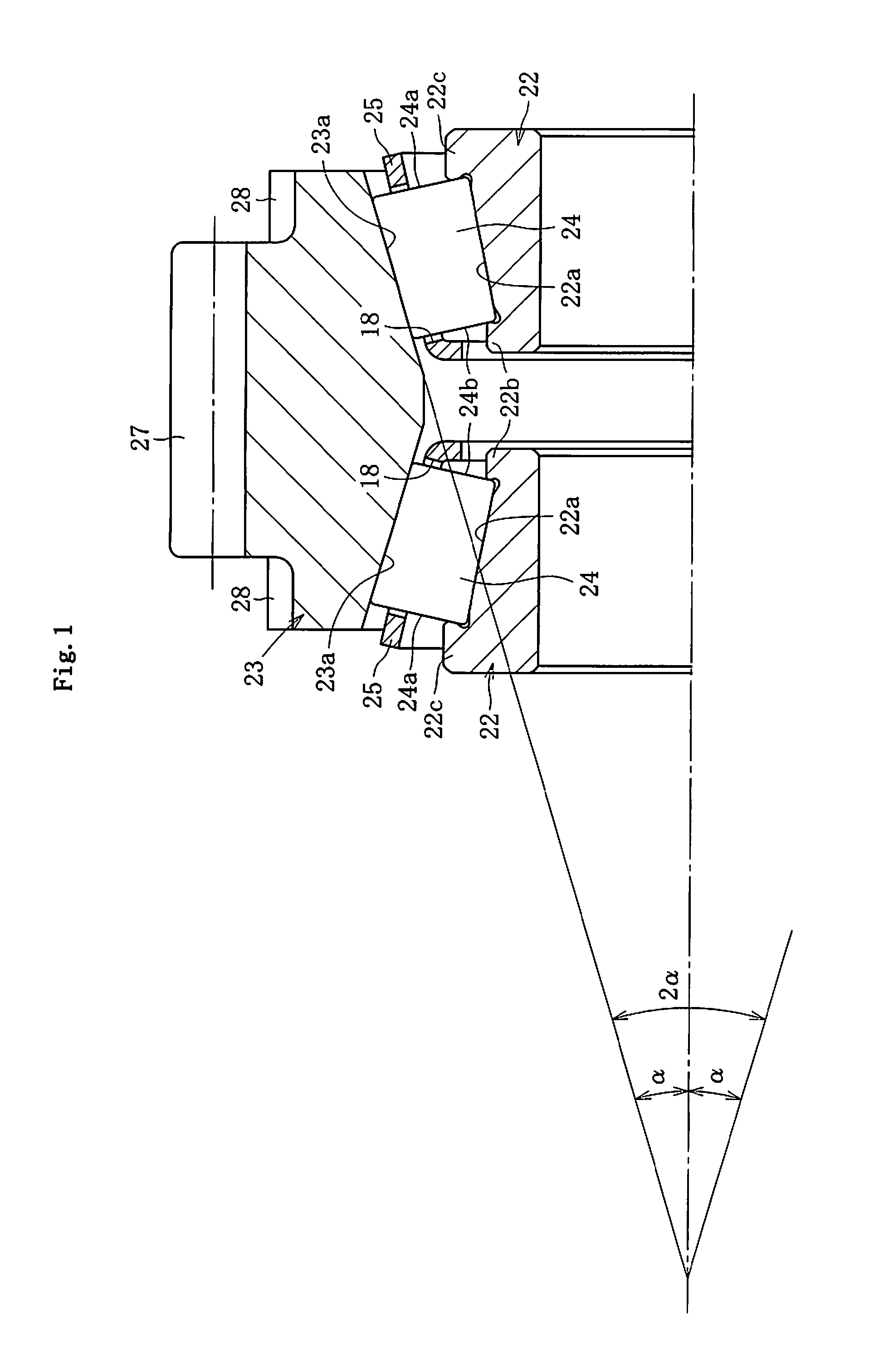
[0068]Sample products were manufactured with various changes made to the outer ring raceway surface angle (2α). The occurrence of fretting in each sample product was examined. The results are shown in the following Table 2. In sample e in Table 2, α=12.5°. In sample f, α=15.0°. In sample g, α=17.5°. In sample h, α=20.0°. In this instance as well, each sample has two types of rollers, the standard rollers and the MoS2 rollers. The standard rollers and the MoS2 rollers in the sample e, and the standard rollers in the sample f are conventional products. The standard rollers and the MoS2 rollers in the other samples g and h, and the MoS2 rollers in the sample f are products of the present invention. In the ordinary conventional products, α≦17° to minimize space and the like.

TABLE 2Maximum contactOccurrence of frettingAsurface pressureStandard rollerMoS2 rollere12.5°2300 MPaYesYesf15°2200 MPaYesMildg17.5°2100 MPaMildNoh20°2000 MPaNoNo

[0069]As is clear from Table 2, the maximum contact su...

example 3

[0071]Sample products were manufactured with various changes made to the ratio of the roller diameter (DW1) to the roller length (L). The occurrence of fretting in each sample product was examined. The results are shown in the following Table 3. In sample i in Table 3, L=10 mm, DW1=8 mm, and L / DW1=1.25. In sample j, L=11.2 mm, DW1=8 mm, and L / DW1=1.40. In sample k, L=15.5 mm, DW1=10 mm, and L / DW1=1.55. In sample 1, L=15.3 mm, DW1=9 mm, and L / DW1=1.70. In sample m, L=18.5 mm, DW1=10 mm, and L / DW1=1.85. In sample n, L=115 mm, DW1=7.5 mm, and L / DW1=2.00. In this instance as well, each sample has two types of rollers, the standard rollers and the MoS2 rollers. The standard rollers and the MoS2 rollers in the samples i, j, and k, and the standard rollers in the sample 1 are conventional products. The standard rollers and the MoS2 rollers in the other samples m and n, and the MoS2 rollers in the sample 1 are products of the present invention. In the ordinary conventional products, L / DW1<1...


PUM


Abstract

A tapered roller bearing includes an outer ring 23, an inner ring 22, a tapered roller 24 interposed between the outer ring 23 and the inner ring 22, and a cage 25 holding the tapered roller 24. The tapered roller bearing is used in an idler portion of an automobile transmission that switches between an idle state in which the outer ring 23 rotates freely in relation to the inner ring 22 and a shift state in which the outer ring 23 rotates synchronously with the inner ring 22. The tapered roller bearing includes a fretting suppressing means configured by a ratio of dynamic load rating Cr to static load rating Cor being set to Cor / Cr≧1.4.

Description

TECHNICAL FIELD[0001]The present invention relates to a tapered roller bearing. In particular, the present invention relates to a tapered roller bearing used in an idler portion of an automobile transmission.BACKGROUND ART[0002]A synchronous mesh-type transmission shown in FIG. 6 is known as an example of a transmission. In the transmission, a main shaft 5 and a countershaft (not shown) disposed in parallel with a predetermined distance therebetween are held in a mission case (not shown) such as to rotate freely. The main shaft 5 interlocks with an output shaft (driving wheel side). The countershaft interlocks with an input shaft (engine side).[0003]A countershaft gear 6 is integrally (or separately) provided on the countershaft. A main shaft gear 1 is mounted on the main shaft 5 with a tapered roller bearing A therebetween, such as to rotate freely. A teeth section 1a that constantly meshes with the countershaft gear 6 is integrally provided in a center portion of the outer circumf...

Claims


Application Information

Patent Timeline
Patent Type & Authority Applications(United States)
IPC IPC(8): F16C19/24F16C19/38F16C33/34F16C33/36F16C33/46F16C33/58F16H57/021F16H57/04
CPCF16C19/38F16C33/4635F16C33/4676F16C33/581F16C2240/00F16C2361/61F16C2240/84F16H3/08F16H57/0031F16C2240/30F16C2240/34F16C2240/40F16C19/386
Inventor MATSUSHITA, TOMOKIKANBORI, YASUHIROUENO, TAKASHI
Owner NTN CORP
Why Eureka
Try Eureka