Osnr monitor device and osnr measurement device

a monitor device and monitor device technology, applied in the field of osnr monitor device and osnr measurement device, can solve the problems of difficult to separate optical signal power and ase power from optical spectrum, complicated optical configuration of optical spectrum analyzer, and inability to ensure reliable monitoring

Inactive Publication Date: 2010-12-23
FUJITSU LTD
View PDF11 Cites 44 Cited by
  • Summary
  • Abstract
  • Description
  • Claims
  • Application Information

AI Technical Summary

Problems solved by technology

However, in the related art described above, there arises a problem in that an optical spectrum analyzer having a complicated optical configuration is required.
Furthermore, since a signal spectrum spreads at a time of signal modulation, it is difficult to separate the optical signal power and the ASE power from the optical spectrum, and therefore, reliable monitoring is not ensured.
That is, since it is difficult to separate an optical signal power and an ASE power from a signal spectrum at a time of signal modulation, reliable monitoring is not performed.
However, in this method, since deterioration of wavelength dispersion, PMD (Polarization-Mode Dispersion), XPM (Cross Phase Modulation), FWM (Four-Wave Mixing), and the like are measured in addition to deterioration of the OSNR, the OSNR is not accurately monitored.

Method used


Image

  • Osnr monitor device and osnr measurement device
  • Osnr monitor device and osnr measurement device
  • Osnr monitor device and osnr measurement device

Examples


first embodiment

[0056]Entire Configuration of Optical Communication System

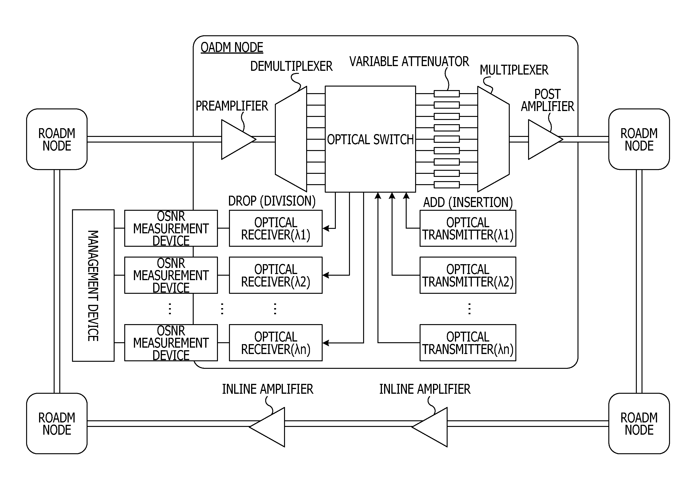
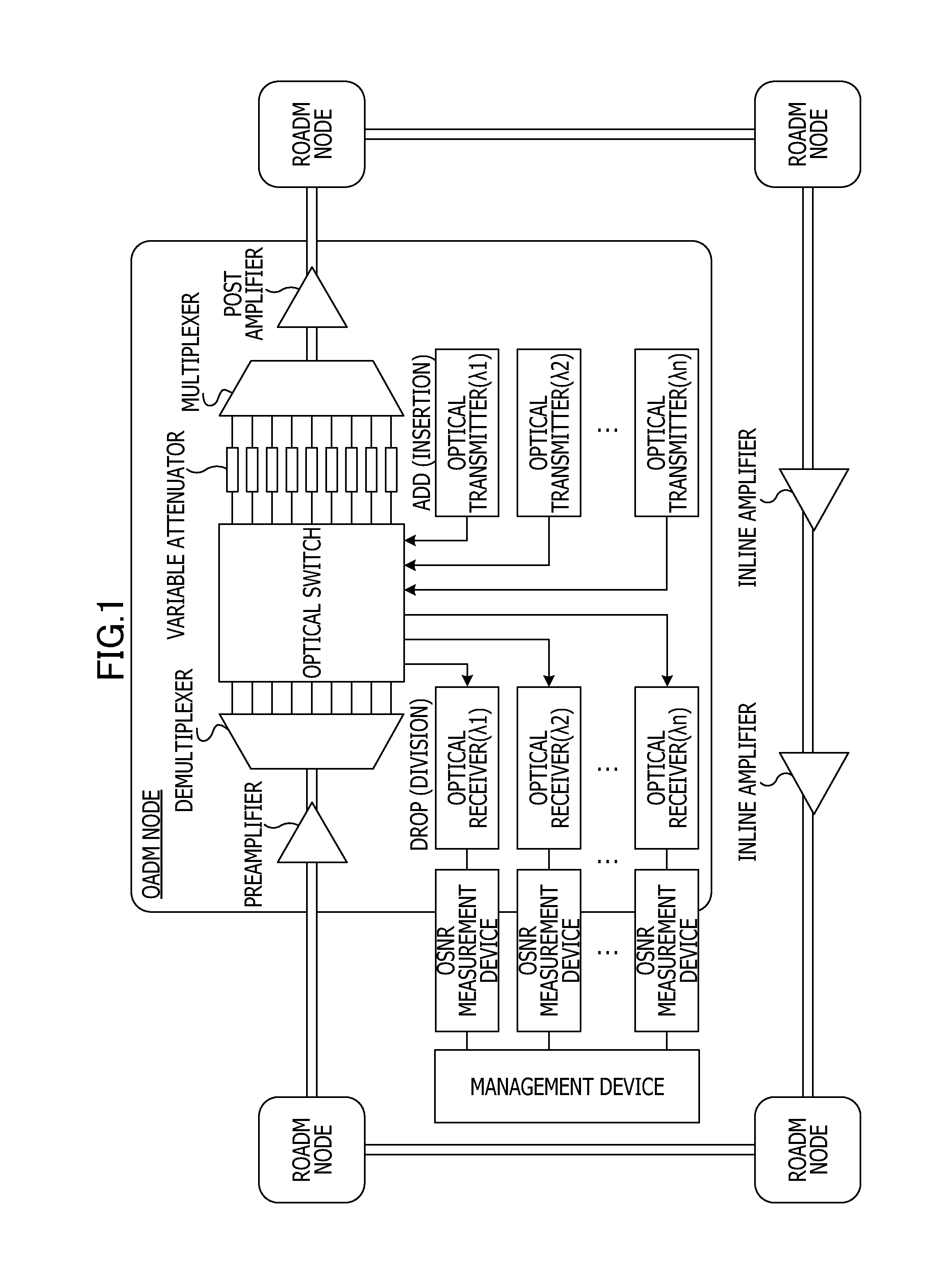
[0057]First, Referring to FIG. 1, an entire configuration of an optical communication system including an OSNR measurement device according to a first embodiment will be described.

[0058]As shown in FIG. 1, in this optical communication system, a plurality of ROADM nodes are connected to one another through a transmission path using an optical fiber, and inline amplifiers used to compensate for a loss of the transmission path are provided between the adjacent ROADM nodes.

[0059]Furthermore, in each of the ROADM nodes, a post amplifier is arranged on an output side (transmitter side) and a preamplifier is arranged on an input side (before a receiver), and a demultiplexer, an optical switch, variable attenuators, and a multiplexer are arranged between the preamplifier and the post amplifier. Note that the demultiplexer demultiplexes a received light beam for individual channels and outputs demultiplexed light beams to the optical...

second embodiment

[0080]In the first embodiment, the optical receiver 10 includes the delay interferometer 11 and the optical detectors (PD1 and PD2). However, the measurement of the OSNR disclosed in this application is not limited to this and receivers having various configurations may be employed.

[0081]In a second embodiment, an example of measurement of an OSNR using a receiver having function units different from the function units described in the first embodiment will be described. Note that the receiver of the second embodiment is also merely an example, and other receivers may be similarly employed.

[0082]For example, as shown in FIG. 4, an optical receiver 10 of an OSNR monitor 1 may include an optical filter 12 in addition to a delay interferometer 11 and optical detectors (PD1 and PD2). FIG. 4 illustrates the OSNR monitor 1 including an optical receiver including the optical filter 12.

[0083]The optical filter 12 corresponds to a band narrower than that of an optical filter included in a de...

third embodiment

[0089]In the second embodiment, the configuration of the optical receiver 30 including the OSNR monitor is illustrated. However, this application is not limited to this configuration and optical receivers having various configurations may be employed.

[0090]For example, as shown in FIG. 6, an optical receiver 30 which is connected to a demultiplexer 2 and which includes a splitter 31, an optical receiver 32, and an OSNR monitor 1 may be employed.

[0091]In the optical receiver 30, an optical signal which has been subjected to filtering performed by the demultiplexer 2 having a function the same as that of the first embodiment is received by the splitter 31. The splitter 31 divides the received optical signal into two branches to be supplied to the optical receiver 32 and the OSNR monitor 1.

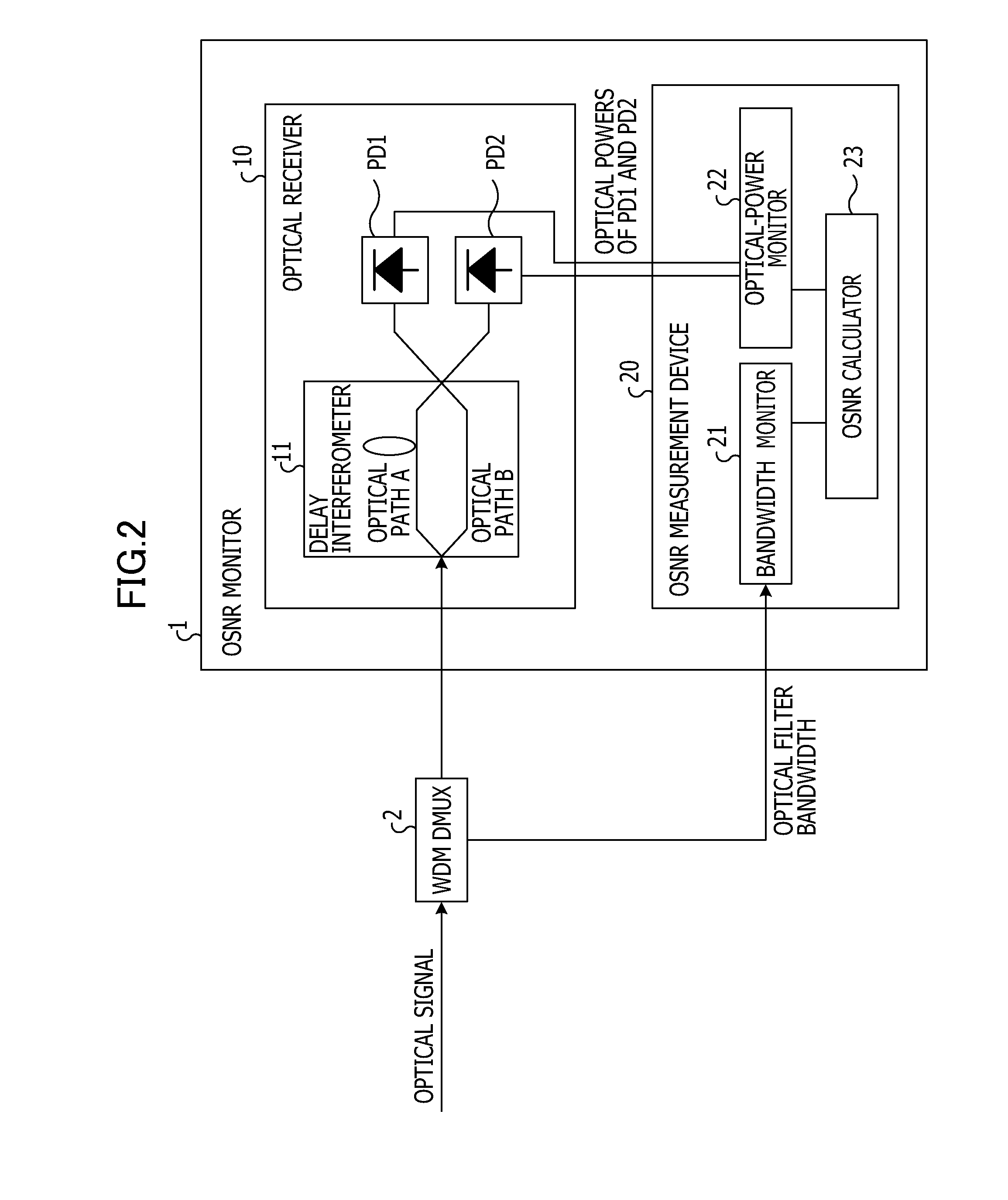
[0092]The OSNR monitor 1 includes a delay interferometer 11, optical detectors PD1 and PD2, and an OSNR measurement device 20 including a bandwidth monitor 21, an optical-power monitor 22, and an OSN...


PUM


Abstract

An OSNR monitor device includes an optical receiver including a delay interferometer which inputs an optical signal in accordance with a given bandwidth and outputs two optical signals and causes the optical signals to interfere with each other and optical detectors which outputs currents in accordance with optical powers of the optical signals output from the interferometer, an optical power monitor configured to obtain the optical powers of the optical signals received by the optical detectors included in the optical receiver, and an OSNR calculator configured to calculate an optical signal-to-noise ratio in accordance with the optical powers obtained from the optical power monitor and the reception bandwidth.

Description

CROSS REFERENCE TO RELATED APPLICATION[0001]This application is based upon and claims the benefit of priority of the prior Japanese Patent Application No. 2009-147016 filed on Jun. 19, 2009, and the prior Japanese Patent Application No. 2010-083786 filed on Mar. 31, 2010, the entire contents of which are incorporated herein by reference.FIELD[0002]Various embodiments described herein relate to an OSNR monitor device and an OSNR measurement device.BACKGROUND[0003]Conventionally, an optical communication system in which a transmitter transmits an optical signal and a receiver receives the optical signal through an optical fiber serving as a transmission path has been used. In such an optical communication system, an optical amplifier is used to compensate for a loss of a transmission path.[0004]The optical amplifier used in the optical communication system includes a post amplifier arranged on an output side of the transmitter, a preamplifier arranged in front of the receiver, or an i...

Claims


Application Information

Patent Timeline
Patent Type & Authority Applications(United States)
IPC IPC(8): H04B10/08H04B10/07G01M11/02H04B10/079H04B10/27H04B10/275H04B10/291H04B10/516H04B10/556H04B10/588H04B10/61H04J14/00H04J14/02
CPCH04B10/07953
Inventor SHUKUNAMI, NORIFUMINAKAMURA, KENTAROMIZUGUCHI, NORIAKI
Owner FUJITSU LTD
Why Eureka
Try Eureka