Sharpened, oriented contact tip structures

a tip structure and oriented technology, applied in the direction of contact members penetrating/cutting insulation/cable strands, coupling device connections, instruments, etc., can solve the problems of b>10/b> horizontal movement of the tip structure, inaccurate voltage levels during device testing, and lower test yields when the contact is contacted

Inactive Publication Date: 2010-12-23
FORMFACTOR INC
View PDF26 Cites 28 Cited by
  • Summary
  • Abstract
  • Description
  • Claims
  • Application Information

AI Technical Summary

Benefits of technology

[0009]An apparatus and method providing improved interconnection elements and tip structures for effecting pressure connections between terminals of electronic components is described. The tip structure of the present invention has a sharpened blade oriented on the upper surface of the tip structure such that the length of the blade is substantially parallel to the direction of horizontal movement of the tip structure as the tip structure deflects across the terminal of an electronic component. In this manner, the sharpened substantially parallel oriented blade slices cleanly through any non-conductive layer(s) on the surface of the terminal and provides a reliable electrical connection between the interconnection element and the terminal of the electrical component.

Problems solved by technology

There are a number of problems associated with achieving the above-described electrical contact.
First, as the terminal contact areas also get smaller, the horizontal movement of the tip structure 10 becomes an issue.
This buildup may contribute to high contact resistance between the tip structure and the terminal, which may cause inaccurate voltage levels during device testing due to the voltage produced across the tip structure.
The inaccurate voltage levels may cause a device to incorrectly fail, resulting in lower test yields when the contact is used in a device testing environment.

Method used


Image

  • Sharpened, oriented contact tip structures
  • Sharpened, oriented contact tip structures
  • Sharpened, oriented contact tip structures

Examples


embodiment 400

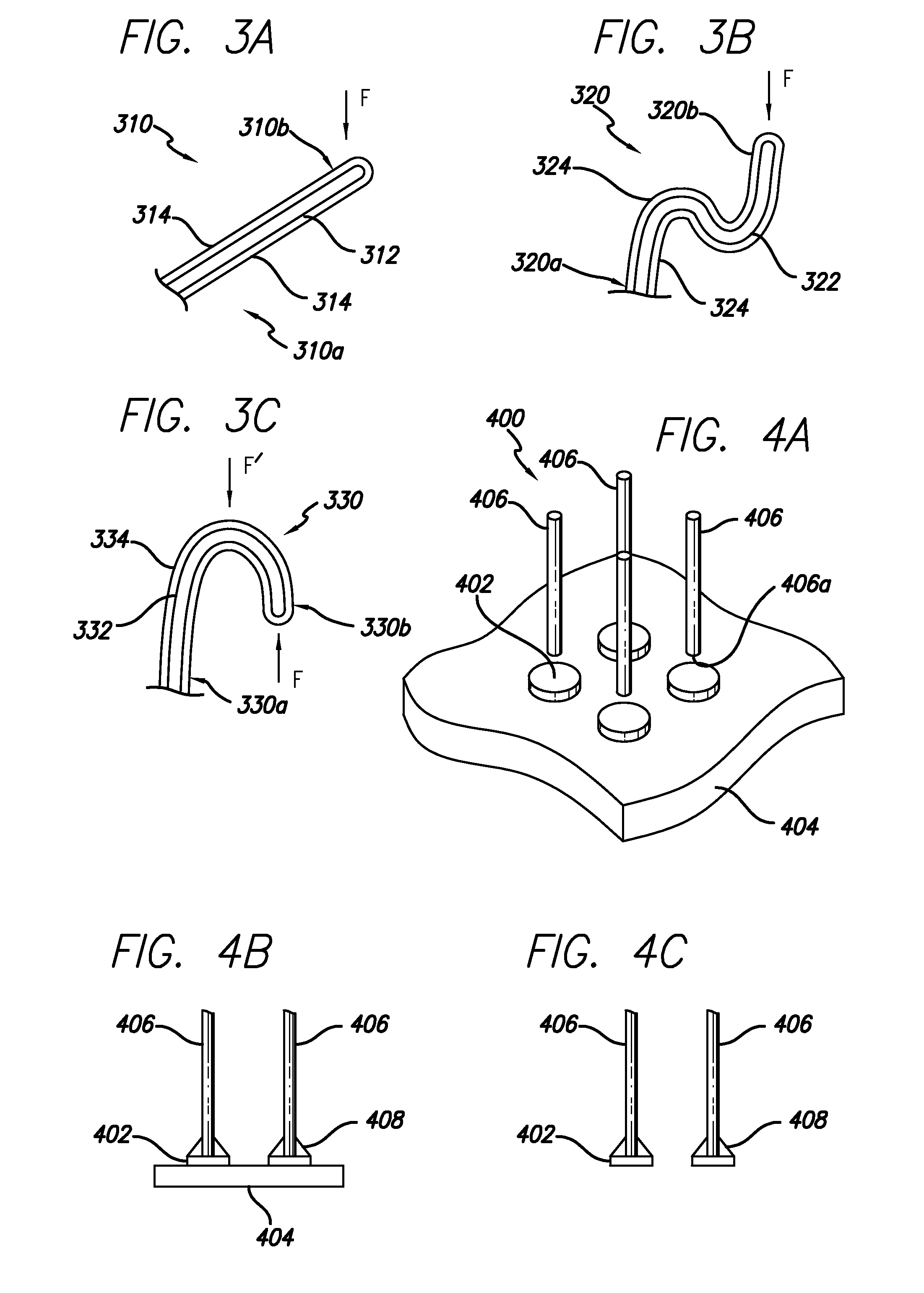
[0060]FIG. 4A illustrates a generalized embodiment 400 of the invention wherein a plurality (four of many shown) of contact tip structures 402 have been pre-fabricated upon a support (sacrificial) substrate 404, in a manner described hereinbelow. A corresponding plurality (four of many shown) of interconnection elements 406 are shown in preparation for having their free ends 406a joined to the contact tip structures 402 (or vise-versa). The free ends 406a of the elongate interconnection elements 406 are distant (distal) from opposite ends (not shown) of the elongate interconnection elements 406 which typically would extend from a surface of an electronic component (not shown) such as a semiconductor device, a multilayer substrate, a semiconductor package, etc.

[0061]FIG. 4B illustrates, in side view, a next step of joining the contact tip structures 402 to the elongate interconnection elements 406 by brazing. A resulting braze fillet 408 is illustrated. The contact tip structures 402...

third embodiment

[0084]FIG. 7C is a side view of the present invention having two or more blades fabricated on a single foot. On tip structure 724, two blades 720 are placed in a juxtaposed position and share a common trench 722 having a stand-off height of H. The juxtaposed blades 720 are particularly useful in situations for fine pitch applications with contact surfaces in close proximity.

[0085]Another embodiment utilizing the present invention is a multi-height blade such as blade 800 shown in FIGS. 8A and 8B. Blade 800 has a primary blade 802 toward the front edge of the tip structure 806, and a trailing blade 804 toward the back of the tip structure 806. The blade 800 may be formed using a masking process wherein the mask surrounding the shorter, trailing blade 804 provides a smaller hole such that the trench etch by the KOH etch is shallow, and the mask surrounding the taller, front blade provides a larger hole such that the trench etch by the KOH etch is deeper and the blade 806 will be talle...


PUM

PropertyMeasurementUnit
thicknessaaaaaaaaaa
thicknessaaaaaaaaaa
angleaaaaaaaaaa

Abstract

An apparatus and method providing improved interconnection elements and tip structures for effecting pressure connections between terminals of electronic components is described. The tip structure of the present invention has a sharpened blade oriented on the upper surface of the tip structure such that the length of the blade is substantially parallel to the direction of horizontal movement of the tip structure as the tip structure deflects across the terminal of an electronic component. In this manner, the sharpened substantially parallel oriented blade slices cleanly through any non-conductive layer(s) on the surface of the terminal and provides a reliable electrical connection between the interconnection element and the terminal of the electrical component.

Description

BACKGROUND OF THE INVENTION[0001]1. Field of the Invention[0002]The present invention relates generally to the field of electrical interconnection (contact) elements, and, more particularly, to interconnection elements and tip structures suitable for effecting pressure connections between electronic components.[0003]2. Description of the Related Art[0004]Generally, interconnections between electronic components can be classified into the two broad categories of “relatively permanent” and “readily demountable”. An example of a relatively permanent connection is a solder joint. Once two electronic components are soldered to one another, a process of unsoldering must be used to separate the components. A wire bond, such as between a semiconductor die and the inner leads of a semiconductor package (or the inner ends of lead frame fingers) is another example of a relatively permanent connection.[0005]One example of a readily demountable connection is rigid pins of one electronic componen...

Claims


Application Information

Patent Timeline
Patent Type & Authority Applications(United States)
IPC IPC(8): H01R11/20H01R4/26G01R1/073H01R12/55H01R12/71H01R13/24H01R43/16
CPCG01R1/06711H01R4/26H01R9/091H01R13/2407Y10T29/49128H01R2201/20G01R1/06727Y10T29/49004Y10T29/49165H01R13/2442H01R12/57H01R4/24H01R12/00
Inventor ELDRIDGE, BENJAMIN N.GRUBE, GARY W.KHANDROS, IGOR Y.MADSEN, ALEXMATHIEU, GAETAN L.
Owner FORMFACTOR INC
Why Eureka
Try Eureka