
Data storage device

a data storage and data technology, applied in the direction of machines/engines, process and machine control, nuclear elements, etc., can solve the problems of inferior fuel use and high possibility, and achieve the effect of improving the workability of analysis and low workability

Active Publication Date: 2010-12-23
DENSO CORP
View PDF10 Cites 13 Cited by
  • Summary
  • Abstract
  • Description
  • Claims
  • Application Information

AI Technical Summary

Benefits of technology

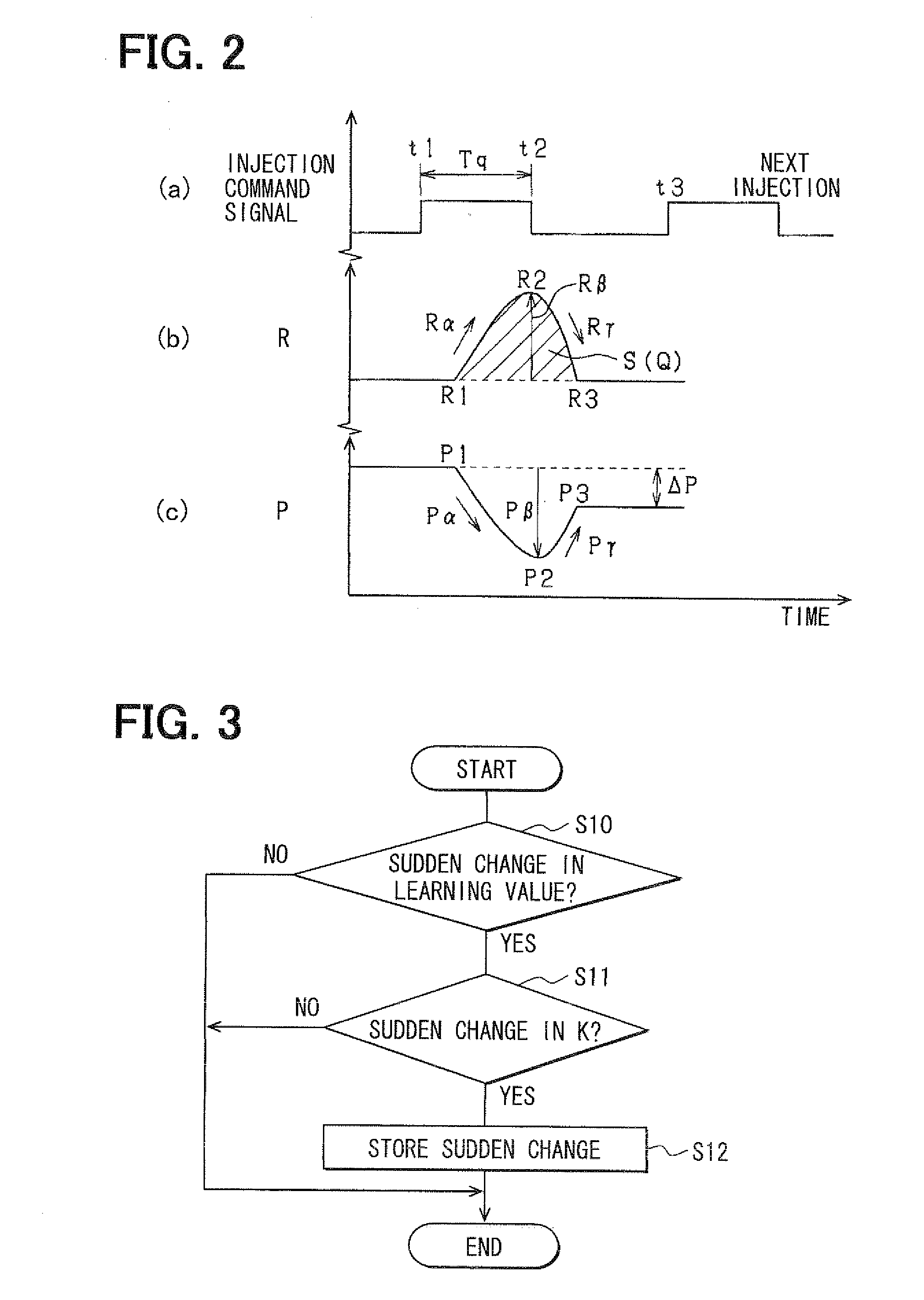
[0010]When it is found that the bulk modulus of the fuel has changed largely, it can be found that the property of the fuel has changed. In such the case, there is a high possibility that inferior fuel was used. According to the above-described aspect of the present invention taking this point into account, the storing section stores the determination result (data) of whether the change amount of the bulk modulus per unit time increases and exceeds the predetermined amount or the value of the bulk modulus (data). Therefore, for example, when the defect such as the inability to inject the desired quantity of the fuel arises, the above-described data can be effectively used for analyzing whether the cause of the defect is the use of the inferior fuel.
[0028]It is common to control the operation of the injector by a control unit (ECU) provided in a place different from the injector. If the above-described various data are stored in the ECU, a defect analysis worker who received the injector causing the defect cannot obtain the various data unless the worker receives also the ECU. Therefore, workability is low in this case. As contrasted thereto, the storing section according to the present invention stores the various data useful for the defect cause analysis and the various data useful for deciding the learning frequency in the storage mounted in the injector. Accordingly, the defect analysis worker can obtain the various data without necessitating the reception of the ECU, thereby improving the workability of the analysis.

Problems solved by technology

In such the case, there is a high possibility that inferior fuel was used.

Method used


Image

  • Data storage device
  • Data storage device
  • Data storage device

Examples


Embodiment Construction

[0037]Hereafter, an embodiment of a data storage device according to the present invention will be described with reference to the drawings. The data storage device according to the present embodiment is mounted in an engine (internal combustion engine) for a vehicle. A diesel engine that injects high-pressure fuel and causes compression self-ignition combustion of the fuel in multiple cylinders #1-#4 is assumed as the engine according to the present embodiment.

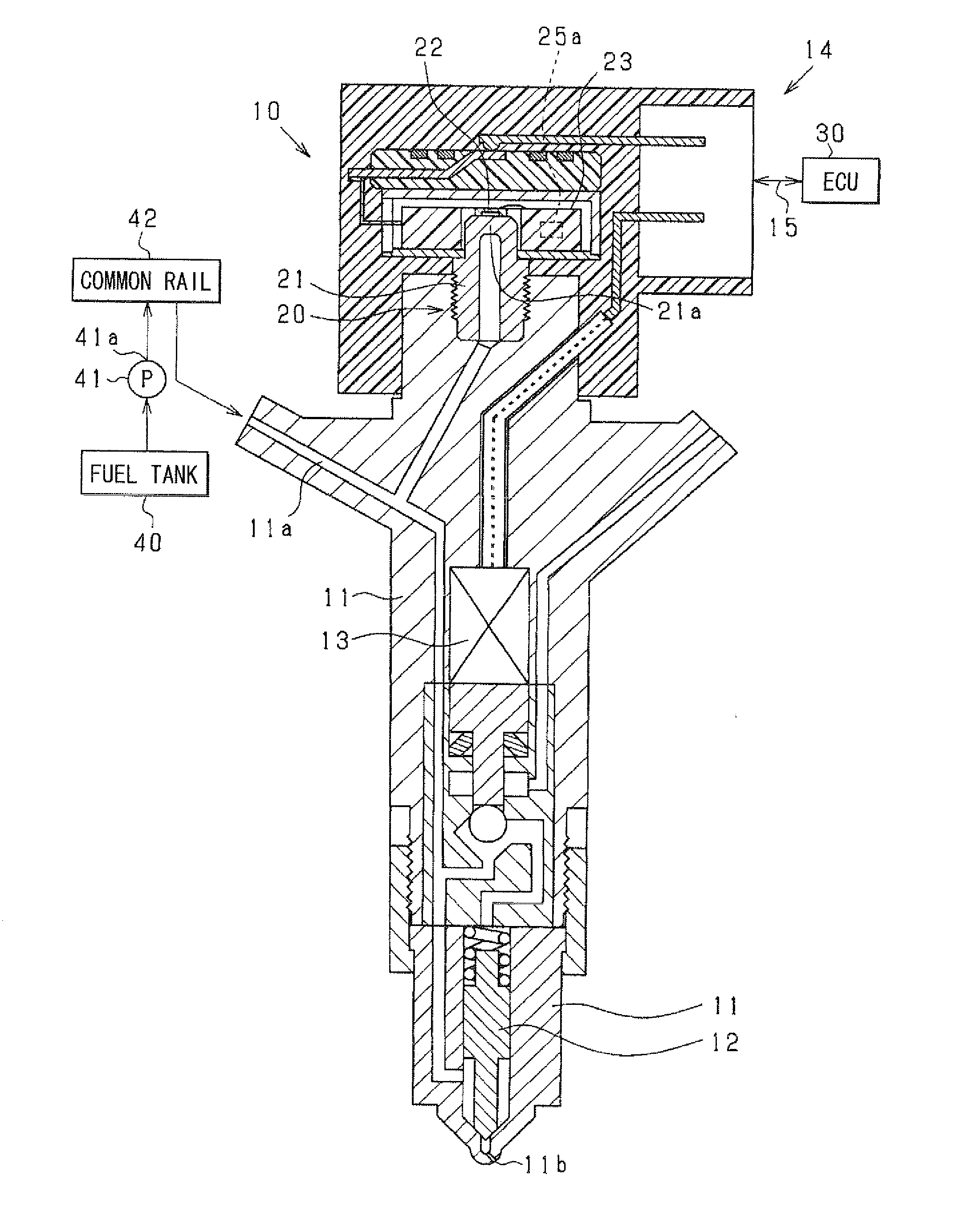
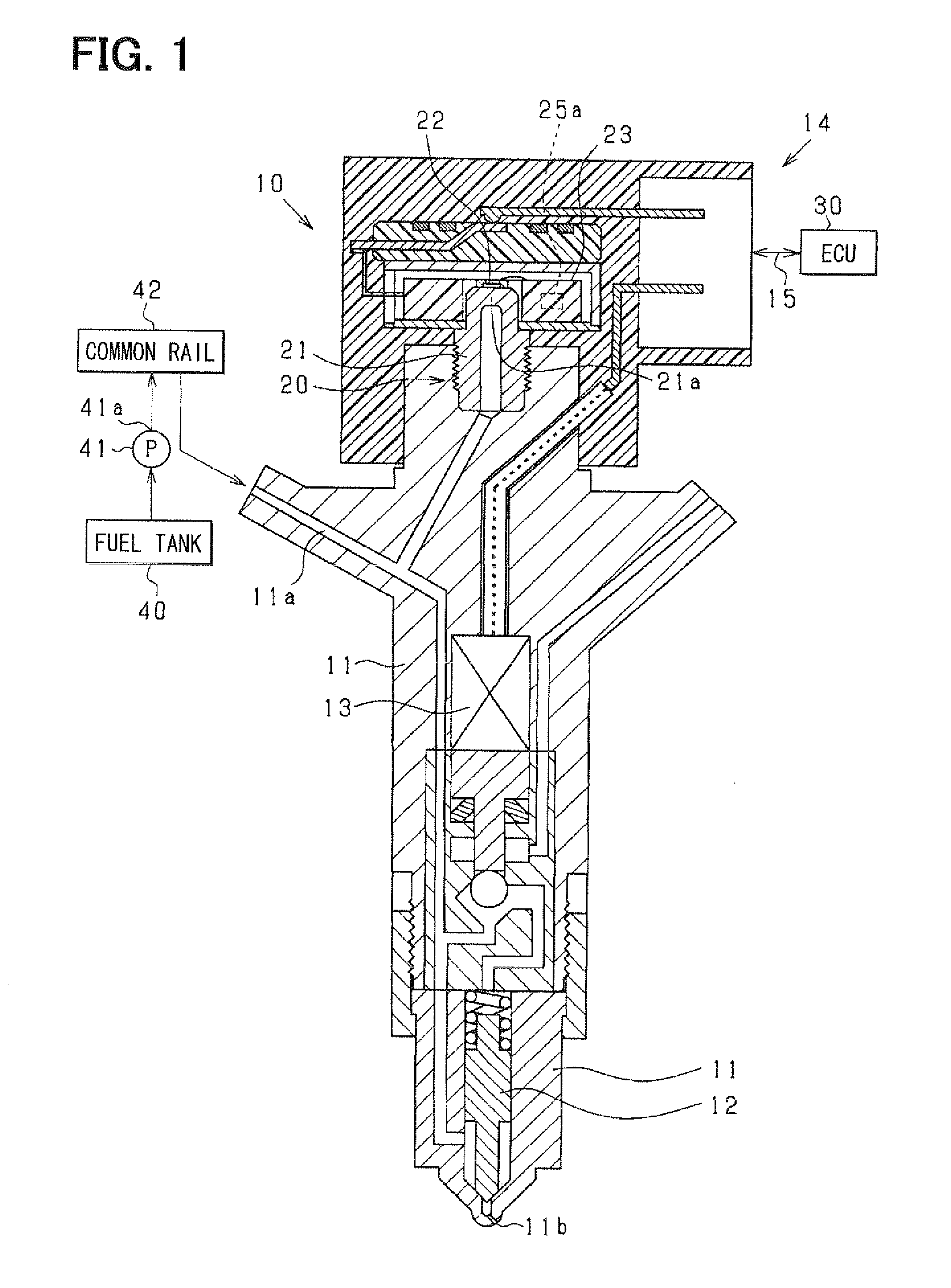
[0038]FIG. 1 is a schematic diagram showing an injector 10 mounted in each cylinder of the engine, a fuel pressure sensor 20 mounted in the injector 10, EEPROM 25a (storage) mounted in the fuel pressure sensor 20, an ECU 30 as an electronic control unit mounted in the vehicle and the like.

[0039]First, a fuel injection system of the engine including the injector 10 will be explained. The fuel in a fuel tank 40 is pumped by a high-pressure pump 41 into a common rail 42 (pressure accumulator) and is accumulated in the common rai...


PUM


Abstract

Data indicating a sudden change in a bulk modulus of fuel and data indicating a usage state and a usage environment of an injector as of occurrence of an injection abnormality are stored in EEPROM mounted in the injector. Thus, it can be analyzed whether a cause of a defect such as the injection abnormality is use of inferior fuel based on the data related to the bulk modulus. In addition, it can be analyzed whether the cause of the defect such as the injection abnormality is a severe usage state and a severe usage environment based on the data related to the usage state and the usage environment. Thus, the data useful for analyzing the cause of the defect related to the fuel injection can be provided.

Description

CROSS REFERENCE TO RELATED APPLICATION[0001]This application is based on and incorporates herein by reference Japanese Patent Application No. 2009-147014 filed on Jun. 19, 2009.BACKGROUND OF THE INVENTION[0002]1. Field of the Invention[0003]The present invention relates to a data storage device that provides various types of data related to an injector of an internal combustion engine.[0004]2. Description of Related Art[0005]There is a case where an injector, for example as described in Patent document 1(JP-A-2009-74536), causes defects such as an inability to inject a desired quantity of fuel. The defects can occur not only because the injector reaches its lifetime but because of other various types of causes. For example, the defects can occur when inferior fuel is used, when the injector is used in a state where an engine operation state becomes a high-load state for a moment, or when the injector is used in a high-load range frequently.[0006]Therefore, replacement of the injecto...

Claims


Application Information

Patent Timeline
Patent Type & Authority Applications(United States)
IPC IPC(8): F02D41/30
CPCF02D19/0628F02D41/0025F02D41/221F02D41/2467F02D2041/224F02D2200/0602F02D19/088Y02T10/36Y02T10/40F02D19/061F02D19/0623F02D19/0689F02D2200/0612F02M2200/8007Y02T10/30
Inventor SUGIYAMA, KOUICHIISHIZUKA, KOJI
Owner DENSO CORP
Learn More