Method and system for protecting an electrical power transmission network

a technology for electrical power transmission networks and protection methods, applied in the direction of electric vehicles, moving iron instruments, instruments, etc., can solve the problems of brownouts, low voltage, and a large number of users to a large number of potential sources of network problems, and achieve the effect of determining the stability of the network

Inactive Publication Date: 2010-12-23
MARTI JOSE R
View PDF15 Cites 43 Cited by
  • Summary
  • Abstract
  • Description
  • Claims
  • Application Information

AI Technical Summary

Benefits of technology

[0046](h) determining the stability of the network using the load impedance and one or more of the Thévenin voltage and positive sequence Thévenin impedance.
[0047]The computer-readable medium can have further statements and instructions stored therein for execution by a processor to instruct a breaker to disconnect the load when the network has a stability that does not meet a selected stability threshold.
[0048]The computer-readable medium can have yet further statements and instructions stored therein for execution by a processor to communicate to a network controller the stability of the network determined by the processor.

Problems solved by technology

While these linked networks provide many advantages, they also expose a larger number of users to a larger number of potential sources of network problems.
Instability can cause brown outs (low voltage conditions) or black outs (complete loss of power) to a portion or all of the network.
Instability can result when loads (e.g. power required by a defined group of users) on the network increase unexpectedly, transmission lines are reduced in power carrying capacity, generators go offline, or transformers at generator, transmission, or distribution substations are reduced in power conversion capacity.
When the conditions giving rise to network problems are poorly understood, operators may shed more load than necessary causing a wider black out than needed, or they may be unable to isolate the problem such that the problem may spread across the network causing a widespread black out.
However, when the measurements are made very close to each other, the differences in measured voltages and currents, particularly with respect to the phase angles, are usually not large enough to produce an accurate approximation of the Thévenin parameters.
Further, if more time is allowed between measurements to improve the accuracy of the approximation, then the assumption that the Thévenin parameters do not change between successive measurements is less accurate and there is additional delay in taking protection action to address network instability.

Method used


Image

  • Method and system for protecting an electrical power transmission network
  • Method and system for protecting an electrical power transmission network
  • Method and system for protecting an electrical power transmission network

Examples


example

Calculating the Voltage Stability Indicators

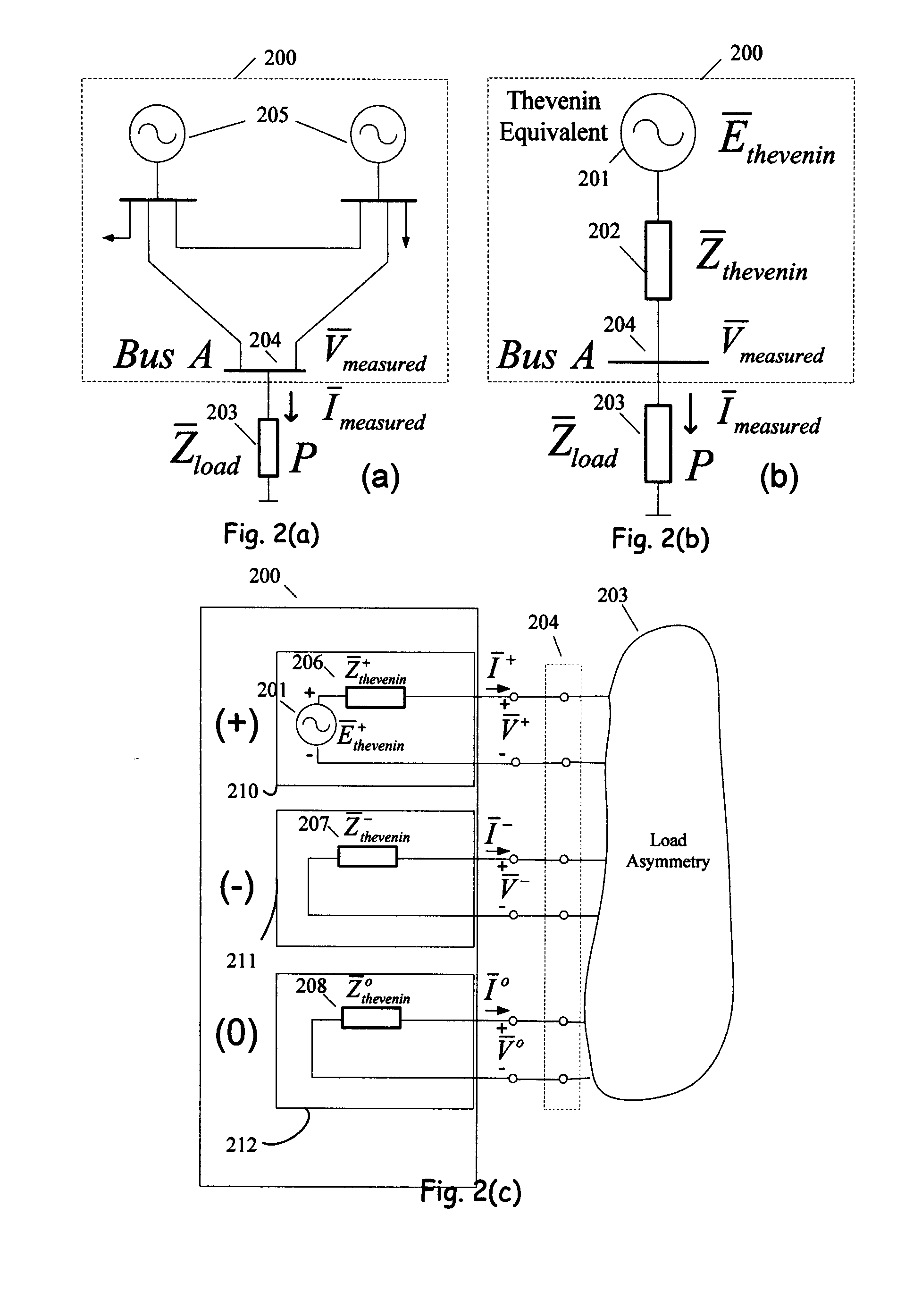
[0109]FIGS. 5 and 6 present data from computer-simulation of the network 200 shown in FIG. 2a. A simulated power-voltage (PV) curve 501 is shown in FIG. 5. The voltage in the PV curve 501 is the positive sequence measured voltage and the power is determined based on the positive sequence measured voltage and the positive sequence measured current. Operating points a, b, . . . j on PV curve 501 correspond to changing values of the active power, P, of load 203 on substation bus 204. Table 5 in FIG. 5 provides a number of computer-simulated quantities associated with operating points a, b, . . . j on PV curve 501. The simulation was conducted using a power factor (pf) at a constant 0.98 lagging for load 203 and an imbalance of 1.5% among load impedances connected to phase a, phase b, and phase c. Using circuit simulation, phase voltages and currents at the bus 204 were calculated (step 401). A symmetrical components transformation was then ap...


PUM


Abstract

A method and system for protecting an electrical power transmission network comprising the steps of: measuring a voltage and a current at a first location in the network other than at a generator in the network; determining positive and negative sequence voltages and currents based on the measured voltage and measured current; determining a negative sequence Thévenin impedance based on the negative sequence measured voltage and negative sequence measured current; defining a positive sequence Thévenin impedance as equal to the negative sequence Thévenin impedance; determining a Thévenin voltage based on the positive sequence measured voltage, positive sequence measured current and the positive sequence Thévenin impedance; determining a load impedance based on the positive sequence measured voltage and positive sequence measured current; and determining the stability of the network using the load impedance and one or more of the Thévenin voltage and positive sequence Thévenin impedance.

Description

FIELD OF INVENTION[0001]The present invention relates to electrical power transmission networks, and more particularly, to a method and system for protecting an electrical power transmission network.BACKGROUND OF THE INVENTION[0002]In the last thirty years, separate electrical power transmission networks within and across countries have been linked together. As a result of deregulation, these linked networks now handle large power transfers across long distances as power is bought and sold in a deregulated market. While these linked networks provide many advantages, they also expose a larger number of users to a larger number of potential sources of network problems.[0003]In order to protect users from network problems the monitoring of network stability is crucial. Instability can cause brown outs (low voltage conditions) or black outs (complete loss of power) to a portion or all of the network. Instability can result when loads (e.g. power required by a defined group of users) on ...

Claims


Application Information

Patent Timeline
Patent Type & Authority Applications(United States)
IPC IPC(8): G06F19/00G01R11/63H02H3/00
CPCH02H3/385G01R21/133G01R19/2513
Inventor MARTI, JOSE R.
Owner MARTI JOSE R
Why Eureka
Try Eureka