Monitoring and feedback control system for laser output stability

A feedback control system and stability technology, applied in the direction of lasers, photometry, laser devices, etc., can solve the problems that the optical system cannot be guaranteed to be normal and stable, and the feedback calibration control cannot be achieved, so as to achieve compact structure and fast feedback adjustment speed , System flexible and variable effects

Pending Publication Date: 2020-10-30
JIANGSU BC-LIGHT PHOTOELECTRIC HIGH-TECH CO LTD
View PDF0 Cites 1 Cited by
  • Summary
  • Abstract
  • Description
  • Claims
  • Application Information

AI Technical Summary

Problems solved by technology

The above adjustments all have hysteresis, and cannot achieve feedback calibration control based on real-time changes in the laser beam
And the above adjustments are only for power, peak power or position deviation, and a single index cannot ensure the normal stability of the optical system

Method used


Image

  • Monitoring and feedback control system for laser output stability

Examples


Embodiment Construction

[0018] The directions shown in the accompanying drawings are up, down, left, and right.

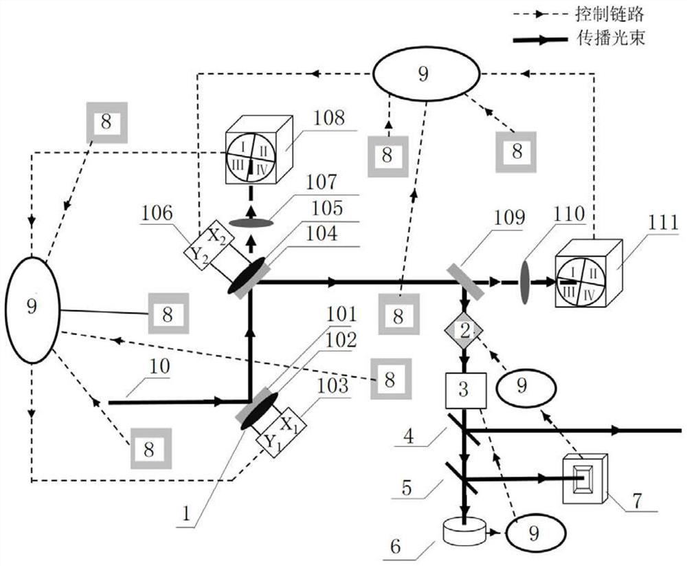
[0019] Such as figure 1 , The monitoring and feedback control system of laser output stability includes three key parts: laser steering device 1, beam detection and circuit control. The laser source emits laser light 10, which is output after being reflected by the first high reflection mirror 101, the second high reflection mirror 104, and the third high reflection mirror 109 of the laser steering device 1, wherein the first high reflection mirror 101 is installed on the first piezoelectric On the driving mirror base 102 , the second high reflection mirror 104 is installed on the second piezoelectric driving mirror base 105 . The laser light 10 passes through the second high reflection mirror 104 and converges on the detection target surface of the first four-quadrant diode 108 through the first focusing lens 107, and the laser light 10 passes through the third high reflection mirror 10...


PUM


Abstract

The invention discloses a monitoring and feedback control system for laser output stability. The monitoring and feedback control system comprises a laser steering device, a dispersion compensation unit, an optical power control unit, a first beam splitter, a second beam splitter, an optical power detector, a peak power detector, an environment monitor and a feedback controller, wherein the laser steering device reflects incident laser for three times, the incident laser sequentially enters the dispersion compensation unit, the optical power control unit, the first beam splitter and the secondbeam splitter and then is split into three beams of light, one beam is emergent light, the other two beams are radiated on the optical power detector and the peak power detector respectively, an output end of the environment monitor is connected with an input end of the feedback controller, and an output end of the peak power detector, an output end of the optical power detector and an output endof the laser steering device are connected with an input end of the feedback controller. The monitoring and feedback control system is advantaged in that real-time stabilization, alignment, positioning and adjustment of laser beams can be realized, and the stable and efficient work of an optical system can be ensured in real time.

Description

technical field [0001] The invention relates to an optical control system, in particular to a monitoring and feedback control system for laser output stability. Background technique [0002] The working performance of the precision optical system is affected by the quality of the beam transmitted in the system. A slight change in the environment will directly cause the deviation of the beam propagation, the change of the optical power and the pulse width, thereby reducing the performance of the optical device. If the system is not corrected in time, it may even be damaged, which often causes fatal damage to the performance of precision optical equipment, such as optical parametric amplifiers, optical parametric oscillators, and transient absorption spectrometers. When the precision optical system encounters the impact of mechanical vibration, humidity, temperature and wind speed changes, the beam pointing and properties will inevitably change. [0003] The existing reported...

Claims


Application Information

Patent Timeline
Patent Type & Authority Applications(China)
IPC IPC(8): H01S3/094H01S3/23G01J1/42
CPCG01J1/4257H01S3/094076H01S3/094084H01S3/2308
Inventor 蔡贞贞仲路铭甘继伟
Owner JIANGSU BC-LIGHT PHOTOELECTRIC HIGH-TECH CO LTD
Why Eureka
Try Eureka