Integrated backlight control system

Inactive Publication Date: 2010-12-30
MICROSEMI
View PDF8 Cites 23 Cited by
  • Summary
  • Abstract
  • Description
  • Claims
  • Application Information

AI Technical Summary

Benefits of technology

[0014]Advantageously, each of the feedback signal and the signals from the video processor are passed through low cost isolating circuits, since there is preferably no requirement for sharp driving edges. Thus, the total cost of the arrangement is preferably reduced as compared to prior art arrangem

Problems solved by technology

With the increasing size of LCDs and the high screen brightness requirements for better display quality, the power consumption of the backlight system becomes a major factor in the total system power consumption of an LCD based monitor or television.
Unfortunately, the above architecture leads to excessive power loss, since an incoming AC line voltage is first converted to a high voltage DC, the high voltage DC is then converted to a low voltage DC, and the low voltage DC is then again converted to a higher AC voltage for driving the luminaires.
The full bridge network can be replaced with a half bridge switching work, thereby reducing cost, however

Method used


Image

  • Integrated backlight control system
  • Integrated backlight control system
  • Integrated backlight control system

Examples


Embodiment Construction

[0032]Before explaining at least one embodiment of the invention in detail, it is to be understood that the invention is not limited in its application to the details of construction and the arrangement of the components set forth in the following description or illustrated in the drawings. The invention is applicable to other embodiments or of being practiced or carried out in various ways. Also, it is to be understood that the phraseology and terminology employed herein is for the purpose of description and should not be regarded as limiting.

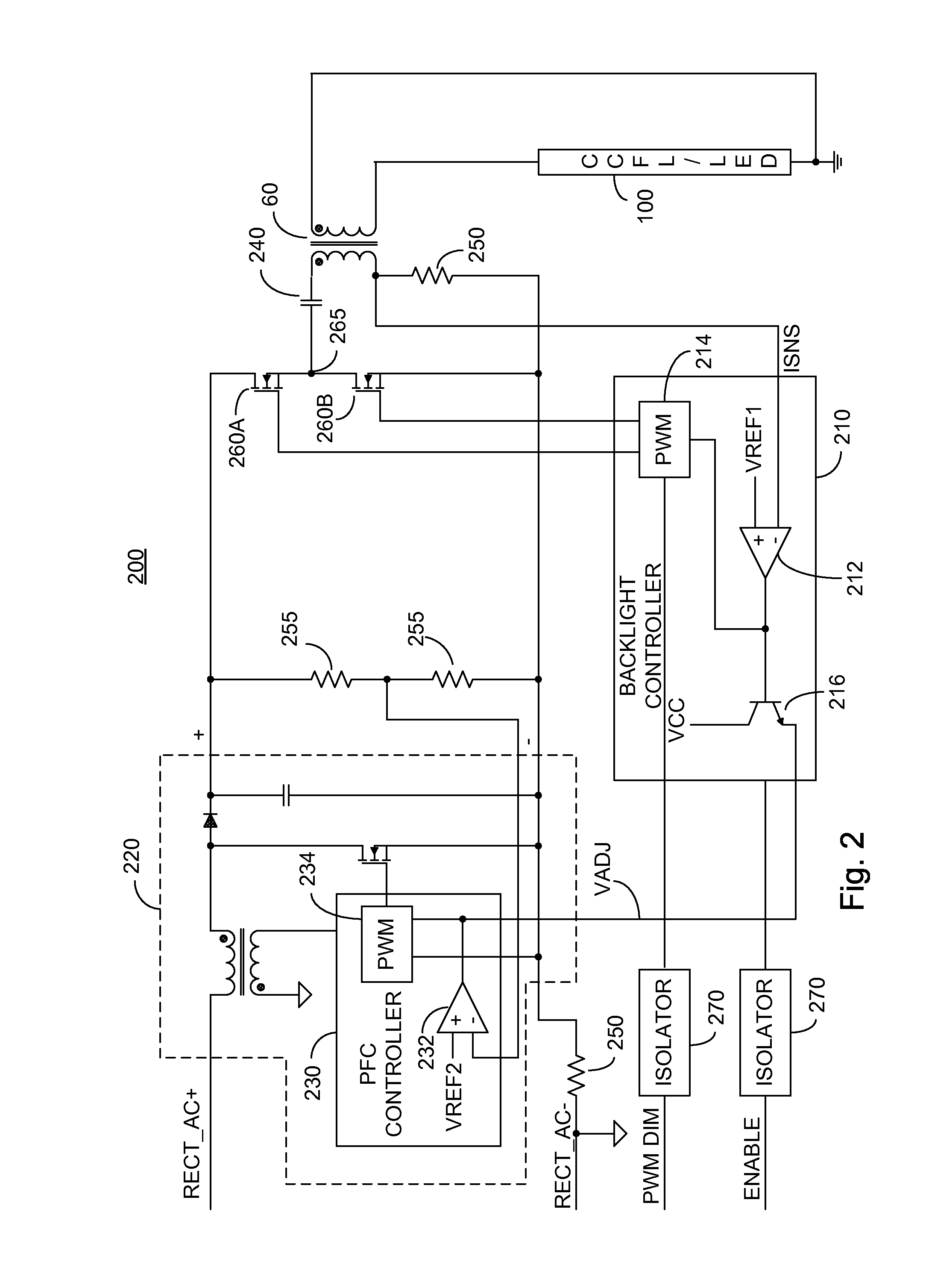
[0033]FIG. 2 illustrates a high level schematic diagram of an embodiment of a driving arrangement 200 in which a backlight controller 210 is provided associated with the PFC circuit side of an isolating transformer, wherein current sensing is accomplished in series with the primary winding of the isolation transformer. Driving arrangement 200 comprises: a backlight controller 210 exhibiting an error amplifier 212, a PWM controller 214 and a dr...


PUM


Abstract

A lighting arrangement constituted of: a power factor correction circuit; a lighting controller operative at an electrical potential consonant with the electric potential of the output of the power factor correction circuit; a switching network, coupled to the output of the power factor correction circuit and to respective outputs of the lighting controller; a transformer, a primary winding of the transformer coupled to the output of the switching network; and at least one luminaire coupled to at least one secondary winding of the transformer and arranged to be driven by the at least one secondary winding, the lighting controller operative to control the switching network via the respective outputs to switchably pass current from the power factor correction circuit through the primary winding, thereby powering the at least one luminaire.

Description

CROSS-REFERENCE TO RELATED APPLICATION[0001]This application claims priority from U.S. Provisional Patent Application Ser. No. 61 / 221,570 filed Jun. 30, 2009, entitled “Integrated CCFL Backlight Control System, the entire contents of which is incorporated herein by reference.TECHNICAL FIELD[0002]The present application relates to the field of lighting, and more particularly to an arrangement in which a lighting controller is connected at a voltage potential associated with a power factor correction stage.BACKGROUND OF THE INVENTION[0003]Fluorescent lamps are used in a number of applications including, without limitation, backlighting of display screens, televisions and monitors. One particular type of fluorescent lamp is a cold cathode fluorescent lamp (CCFL). Such lamps require a high starting voltage (typically on the order of 700 to 1,600 volts) for a short period of time to ionize a gas contained within the lamp tubes and fire or ignite the lamp. This starting voltage may be ref...

Claims


Application Information

Patent Timeline
IPC IPC(8): H05B41/36
CPCY02B20/186H05B41/2828Y02B20/00
Inventor JIN, XIAOPING
Owner MICROSEMI
Why Eureka
Try Eureka