
Remote temperature sensing device

Inactive Publication Date: 2010-12-30
AUTOVISION TECH LTD
View PDF9 Cites 131 Cited by
  • Summary
  • Abstract
  • Description
  • Claims
  • Application Information

AI Technical Summary

Benefits of technology

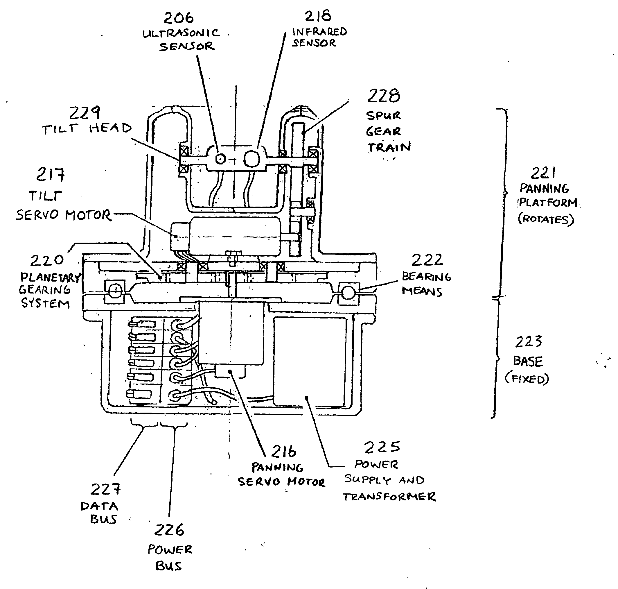
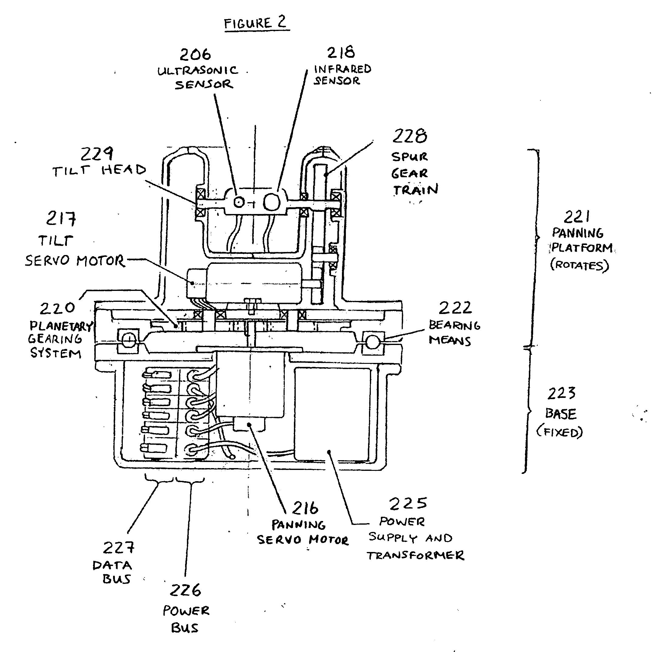
[0017]a support for supporting the distance sensor, the temperature sensor and the digital image capture device;wherein the controller tilts the distance sensor using the tilting means, by identifying the position of the identifying feature in the image, determining the location of the target zone based on the distance to the subject and the position of the identifying feature in the image, and then tilting the distance sensor to reduce the distance between the target zone and the sensing zone.

Problems solved by technology

Such technologies have included thermometers, but thermometers have been problematic in a high-volume screening environment for two reasons.
First, they are slow to react, which increases the time to measure temperature and thereby also increases operator error.
Second, thermometers are difficult to sterilize because they come into direct contact with the subject.
The increased chance of erroneous measurements and the problems with sterilization thereby greatly increase the chance of the spread of some contractual illnesses.
One of the principal challenges of using such methods is testing large numbers of individual subjects passing through a transportation hub or other building for symptoms of illness.
The process can be slow if each individual has to be tested separately.
There are three main difficulties with such devices.
Because there is no facility to measure accurately the subject's distance in existing devices, the subject and operator usually do not know if a reading is erroneous.
This time frame is typically too long to effectively test large numbers of subjects and prevent the spread of disease, while maintaining flow through such facilities.

Method used


Image

  • Remote temperature sensing device
  • Remote temperature sensing device
  • Remote temperature sensing device

Examples


Embodiment Construction

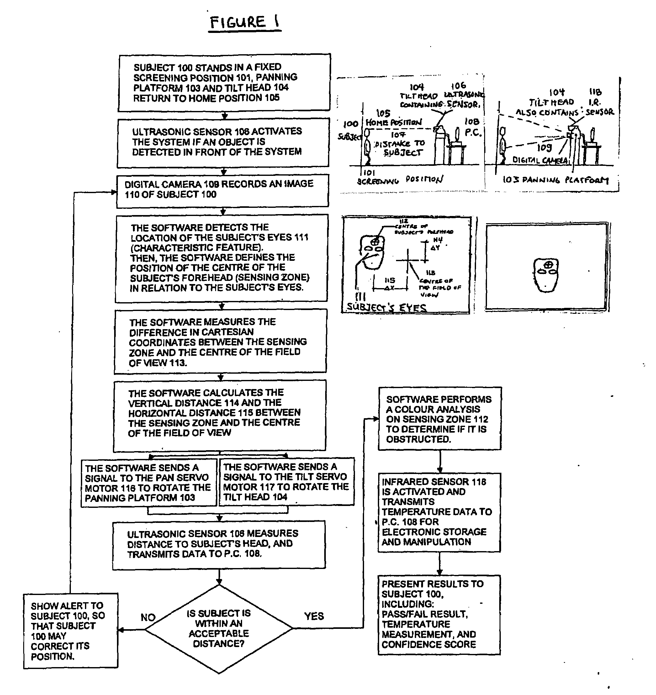
[0023]FIG. 1 shows a flow chart of the process that may be followed by one embodiment of the present invention while in service. In this embodiment, a subject 100 stands in a fixed screening position 101. The panning platform 103 and tilt head 104 return to the home position 105, which is located approximately at the height of an average subject.

[0024]The invention includes a means of detecting the presence of a subject in front of the device. In this embodiment, the ultrasonic sensor 106 is active and transmits a signal to the PC 108 as soon as a subject steps in front of the device. Alternate sensing means may be used to detect the subject's presence, including other optical sensors, position sensors, or mechanical switches located at the screening position 101. In addition, the subject may be detected by being required to push a button, pull a trigger or step on a pedal.

[0025]The invention includes a means of capturing and storing a digital image. In this embodiment, a digital ca...


PUM


Abstract

A temperature sensing device for remotely detecting the temperature of a subject having an identifying feature and a target zone in a fixed relationship to the identifying feature comprising: a distance sensor which measures the distance between the subject and the distance sensor; a temperature sensor for measuring a temperature difference in a sensing zone; a digital image capture device for capturing a digital image of the subject; a means of tilting at least the temperature sensor along at least one axis, and preferably tilting and panning along two axes; a controller that actuates the tilting means; and a support for supporting the distance sensor, the temperature sensor and the digital image capture device; wherein the controller tilts the distance sensor using the tilting means to reduce the distance between the target zone and the sensing zone; and a temperature sensor that measures a temperature difference proximate to the target zone, to detect elevated temperature illness in humans or animals.

Description

FIELD OF THE INVENTION[0001]A remote temperature sensing device for measuring the temperature of an individual or an animal at a distance.BACKGROUND OF THE INVENTION[0002]In airports, train stations and in other places of mass transportation for humans and for animals (‘subjects’), it is known to screen individuals or animals for elevated temperature or other signs of illness. This is done to curtail the spread of illness caused by infectious disease.[0003]In the past, such screening was done initially through subjective observation. A screening officer would simply observe a subject and look for signs of illness such as sweating, disorientation, flushed skin tone and coughing as indications that such a subject is ill and should be isolated from other subjects passing through the transportation hub.[0004]More recently, there have been several technologies developed for screening subjects by measuring temperature, because elevated body temperature is a strong general indication of il...

Claims


Application Information

Patent Timeline
IPC IPC(8): G01J5/00G01S15/00
CPCA61B5/015G01J5/0022G01J5/0025G01J5/02G01J5/0275G01J5/089G01J5/047G01J5/08G01J5/0846G01J5/0859G01J5/04G01J5/07
Inventor PANG, YUK-WALEUNG, HO-WAI PHYLLISCHAN, CHUN-KONG JOSEPHKONG, KIN WAHWONG, YAT-PUILI, KIN-IP
Owner AUTOVISION TECH LTD
Learn More