X-ray inspecting apparatus and x-ray inspecting method
a technology of x-ray inspection and x-ray inspection, which is applied in the direction of material analysis using wave/particle radiation, x/gamma/cosmic radiation measurement, instruments, etc., can solve the problems of difficult to increase the operation speed of the mechanism, complicated mechanism, and difficult to move at high speed, so as to achieve high maintainability, reduce the number of movable parts, the effect of high speed
- Summary
- Abstract
- Description
- Claims
- Application Information
AI Technical Summary
Benefits of technology
Problems solved by technology
Method used
Image

Examples
embodiment 1
Modification of Embodiment 1
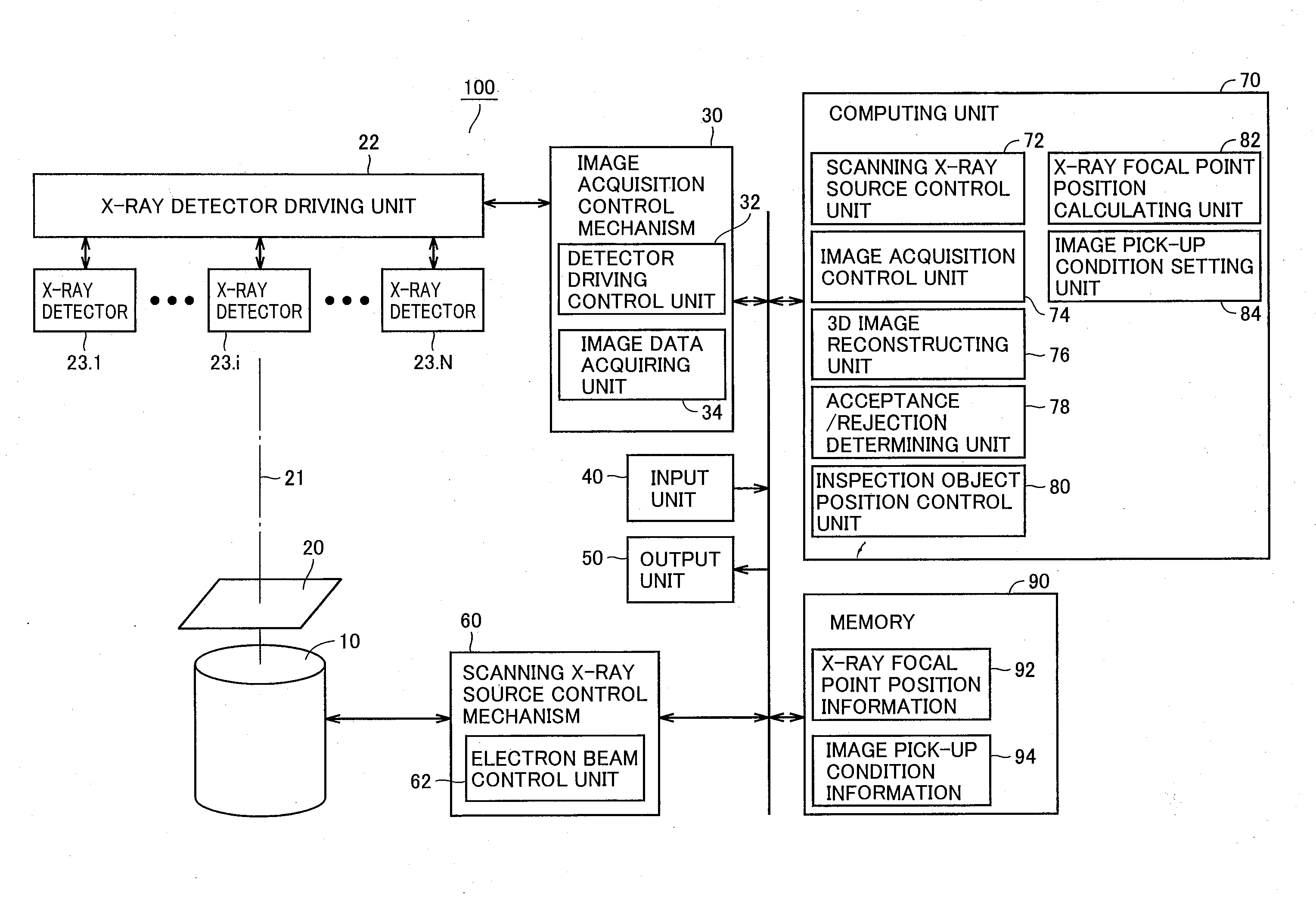
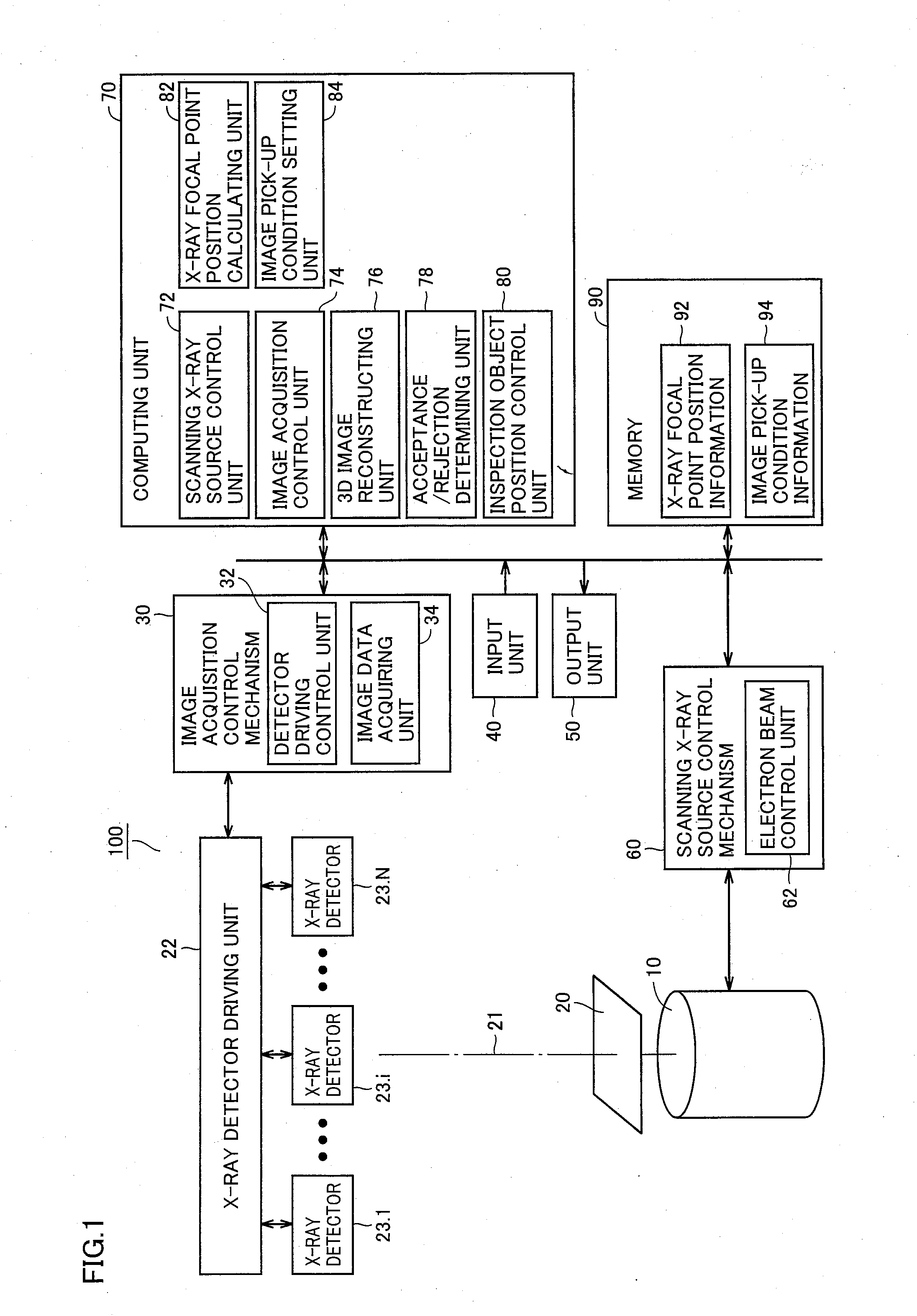
[0270]FIG. 15 illustrates a configuration of an X-ray inspecting apparatus 102 in accordance with a modification of Embodiment 1. In X-ray inspecting apparatus 102, linear type X-ray detectors and a scanning X-ray source as X-ray source 10 are used.
[0271]Specifically, in X-ray inspecting apparatus 102, three X-ray detectors 23.1, 23.2 and 23.3 are each capable of Y-movement and θ rotation, independently from each other. FIG. 15 shows an operation mechanism of X-ray detector driving unit 22 in which X-ray detector supporting unit 22.3 is rotatable and movable on a rail in Y direction. Any mechanism other than that shown in FIG. 15 having the same function may be used without any problem. Further, the rotating mechanism is not always necessary, as will be described later.
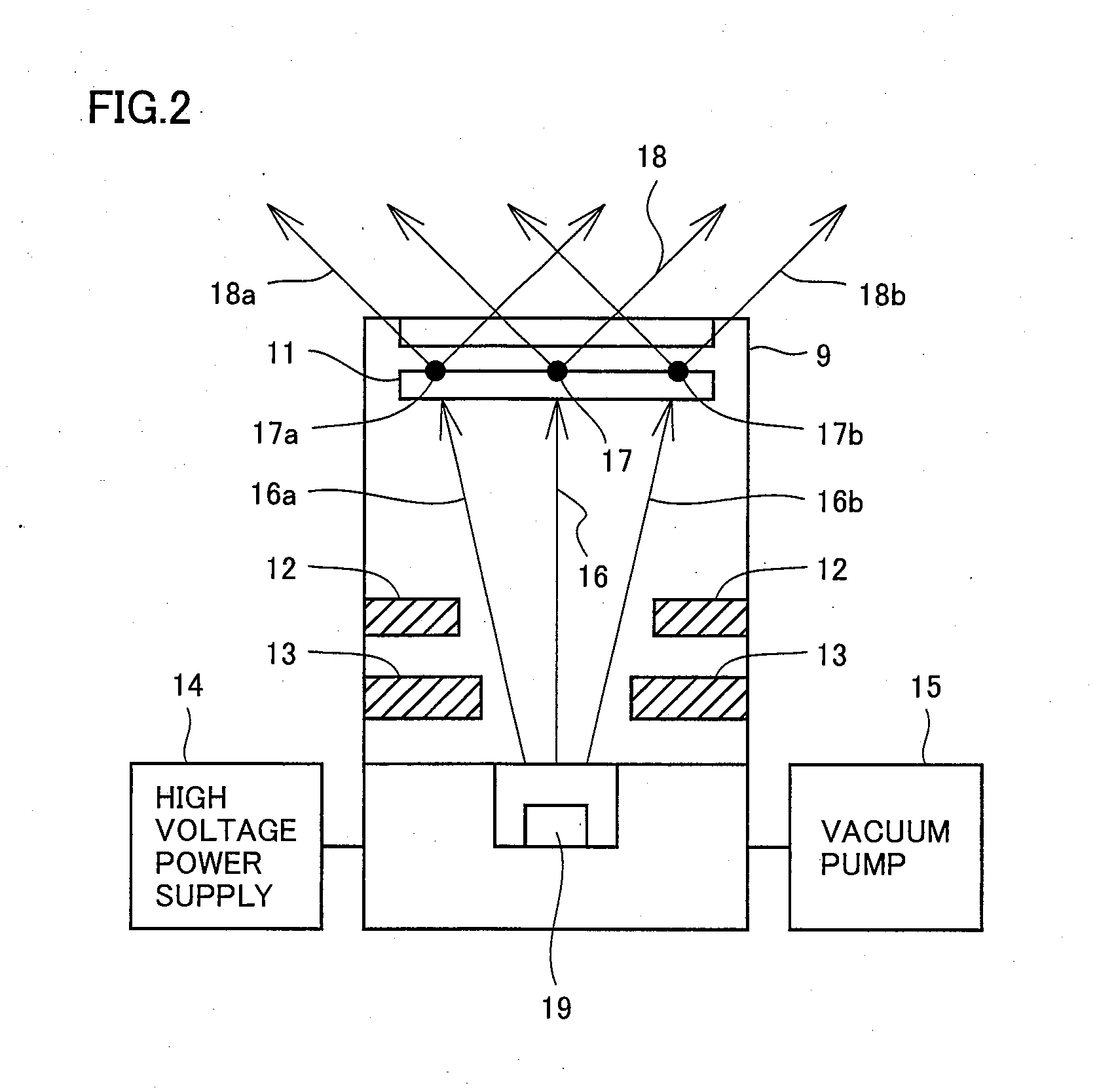
[0272]The scanning X-ray source as X-ray source 10 is capable of moving the X-ray focal point position at high speed to an arbitrary position on the X-ray target.
[0273]Further, the same por...
embodiment 2
[0317]In X-ray inspecting apparatus 102 in accordance with the modification of Embodiment 1, linear type X-ray detectors and scanning X-ray source as X-ray source 10 are provided.
[0318]In X-ray inspecting apparatus 104 in accordance with Embodiment 2, in place of the scanning X-ray source, a plurality of fixed focus X-ray sources are used as X-ray source 10.
[0319]FIG. 20 illustrates a configuration of an X-ray inspecting apparatus 104 in accordance with Embodiment 2.
[0320]In X-ray inspecting apparatus 104, corresponding to three X-ray detectors 23.1 to 23.3 provided as X-ray detector 23, three fixed-focus X-ray sources are provided as X-ray source 10.
[0321]From these three fixed-focus X-ray sources, X-rays are emitted simultaneously to the same field of view of the object of inspection. Here, in order to prevent X-ray from an X-ray source directing the X-ray to be incident on one X-ray detector from entering other X-ray detector, a shield 66 is provided. In addition, for controlling...
embodiment 3
[0365]In Embodiment 1 or Embodiment 2 described above, the effect of reducing inspection time has been discussed mainly from the viewpoint of the time of moving X-ray detector 23 and the object of inspection in CT image pick-up for one field of view.
[0366]In Embodiment 3, reduction of inspection time when a plurality of fields of view (portions to be inspected) of one object of inspection are inspected successively will be described.
[0367](Problems when Images are Picked-Up with Field of View (Object of Inspection) or X-Ray Detector Rotated)
[0368]Considering an imaging system using the analytical method, it is preferred that the direction of X-ray detector is along a circular orbit, about the center of reconstruction area, from the relation of filtering for reconstruction.
[0369]Therefore, when the X-ray detector is to be moved for picking up images from a plurality of angles, it may be moved i) on the circular orbit with the area of reconstruction being the center, or ii) using an X...
PUM
 Abstract
Description
Claims
Application Information
 - R&D
- Intellectual Property
- Life Sciences
- Materials
- Tech Scout
- Unparalleled Data Quality
- Higher Quality Content
- 60% Fewer Hallucinations
Browse by: Latest US Patents, China's latest patents, Technical Efficacy Thesaurus, Application Domain, Technology Topic, Popular Technical Reports.
© 2025 PatSnap. All rights reserved.Legal|Privacy policy|Modern Slavery Act Transparency Statement|Sitemap|About US| Contact US: help@patsnap.com