Apparatus for multi-staged hydroprocessing

a hydroprocessing apparatus and multi-stage technology, applied in the direction of chemistry apparatus and processes, liquid-gas reaction processes, organic chemistry, etc., can solve the problems of increasing capital and operating costs of the hydroprocessing apparatus, adding complexity, increasing capital costs, etc., and achieving high externally recycled product volume, high overall liquid process flow volume, and high efficiency

Inactive Publication Date: 2010-12-30
UOP LLC
View PDF99 Cites 10 Cited by
  • Summary
  • Abstract
  • Description
  • Claims
  • Application Information

AI Technical Summary

Benefits of technology

[0013]As with the method and apparatus above, hydrogen is added only at the beginning of the process in an amount effective to provide sufficient hydrogen for each of the hydroprocessing reactor zones and an additional quantity of hydrogen to minimally maintain the reactor effluent in two phases. When this hydrogen is added at the beginning of the process, the portion of the fresh feed to the first reaction zone ensures that the reaction zone is a substantially three-phase reaction zone. The hydrogen in the process stream is consumed in each reaction zone, and therefore subsequent reactions zones may be substantially liquid-phase reaction zones. Such reaction zones are in a substantially liquid phase throughout. Thus, these aspects also virtually eliminate the need for hydrogen recycle gas compressors and the accompanying cost and other inefficiencies.
[0014]In another aspect, the ratio of the treated effluent to the untreated fresh feed for each reaction stage may be significant and may be different for different reaction stages, for example, the ratios may be 3 to 1, 5 to 1 or 10 to 1 or greater, depending on the needs of the particular reaction stage. These ratios can be obtained as only a portion of the feedstock is introduced at each reaction stage, and the treated effluent, which acts as a diluent and hydrogen carrier, is provided from the preceding reaction stage. Thus, the methods and apparatus herein provide high ratios of treated effluent to untreated feed without correspondingly high externally recycled product volumes. Thus, relatively high overall liquid process flow volumes, or the need for high volume, high capacity recycle pumps and related apparatuses may be avoided. In one such aspect, the hydrogen requirement may be obtained from an external source, such as a make-up gas compressor. The make-up hydrogen flow may be supplied directly to the substantially three-phase hydroprocessing zone and is supplied in an amount sufficient to satisfy the requirements of the substantially three-phase reaction zone. The make-up hydrogen flow also provides excess hydrogen in an amount sufficient to satisfy the requirements of the subsequent substantially liquid-phase hydroprocessing zones.
[0015]Accordingly, the methods and apparatus satisfy the hydrogen requirements of the reaction zones without using a hydrogen recycle gas compressor. They further reduce or eliminate the need for heat exchangers, recycled liquid or gas quench streams, or other temperature control devices between or in the process flow path. Indeed, the methods and apparatus use the unheated feed as quench to the second and perhaps each subsequent reaction zone after the first reaction zone to moderate the temperature of the process stream through all of the reaction zones. As a result, considerable cost savings and operational efficiencies may be achieved by reducing or eliminating the need for heat exchangers in the reaction zones, and the accompanying maintenance difficulties and expense.

Problems solved by technology

However, supplying such large supplies of gaseous hydrogen at the operating conditions needed for hydroprocessing adds complexity and capital and operating expense to the hydroprocessing apparatus.
The recycle gas compressor commonly recirculates hydrogen within the hydroprocessing unit in amounts significantly in excess of the hydrogen used by the reactor circuit due to chemical hydrogen consumption.
Often such hydrogen recycle can be up to about 1685 Nm3 / m3 (10,000 SCF / B, and processing such quantities of hydrogen through a high-pressure compressor adds complexity, increased capital costs, and increased operating costs to the hydroprocessing unit.
Such systems, however, require large volumes of product to provide the desired ratios of the recycled product to the untreated feed.
Maintaining such large ratios of recycled product to untreated feed presents difficulty in the design for larger hydroprocessing units.
In many instances, the combined recycled product and untreated feed flow could exceed a single train capacity limit of the unit.
Thus such units impose additional expense for large capacity recycle pumps and similar apparatuses, as well as related operational issues to permit such large volumetric flows.
While two-phase systems can operate without a costly recycle gas compressor, the reactions in such two-phase systems are generally less efficient, with less contact time between the unconverted oil and the catalyst than similar reactions in the more common substantially three-phase systems.
As a result, the reaction rates in the liquid-phase systems are less efficient and reduced from those in a substantially three-phase system with a similar amount of catalyst.

Method used


Image

  • Apparatus for multi-staged hydroprocessing

Examples


example

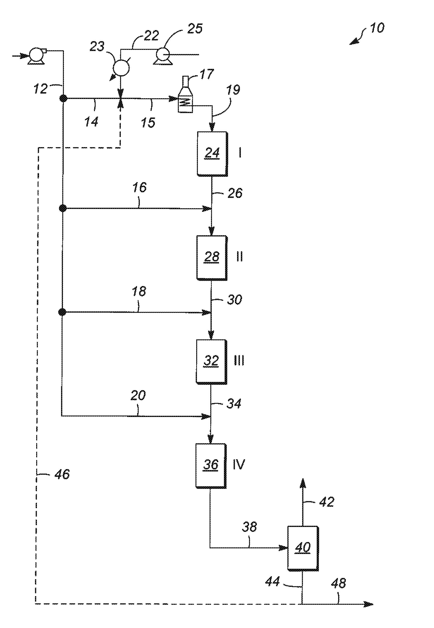
[0062]One example provided below illustrates aspects of the methods and apparatuses discussed above they may be applied to hydrotreating processes using trickle bed, substantially three phase reactors and substantially liquid phase reactors. The example provides data concerning the process flows, process flow temperatures, etc. based on a fresh feedstock rate and catalyst bed distributions, and process flow temperature increases based on a computer simulation developed from actual operating experiences with similar hydrotreating reactors and feedstocks. The feedstock in the example is a vacuum gas oil with the following properties: API Gravity=19.8, Distillation (ASTM D-1160) IBP=725° F. (385° C.), 10%=752° F. (400° C.), 30%=797° F. (425° C.), 50%=833° F. (445° C.), 70%=878° F. (470° C.), 90%=986° F. (530° C.), EP=1022° F. (550° C.) containing 3.5 wt-% sulfur and 600 wppm total nitrogen. In the example the feedstock is lydrotreated to a product which would contain nominally between ...


PUM


Abstract

Apparatuses for processing a hydrocarbonaceous feedstock flows are provided. In one aspect, the method includes providing two or more hydroprocessing stages disposed in sequence, each hydroprocessing stage having a hydroprocessing reaction zone with a hydrogen requirement and each stage in fluid communication with the preceding stage. A hydrogen source is provided substantially free of hydrogen from a hydrogen recycle compressor. The hydrocarbonaceous feedstock flow is separated into an portions of fresh feed for each hydroprocessing stage, and the first portion of fresh feed to the first hydroprocessing stage is heated. The heated first portion of fresh feed is supplied with hydrogen from the hydrogen source in an amount satisfying substantially all of the hydrogen requirements of the hydroprocessing stages to a first hydroprocessing zone. The unheated second portion of fresh feed is admixed with effluent from previous stage to quench the hot reactor effluent before entering a second stage.

Description

FIELD OF THE INVENTION[0001]The field generally relates to hydroprocessing of hydrocarbon streams and, more particularly, to hydroprocessing using multiple hydroprocessing stages.BACKGROUND OF THE INVENTION[0002]Petroleum refiners often produce desirable products such as turbine fuel, diesel fuel, middle distillates, naphtha, and gasoline, among others, by hydroprocessing a hydro-carbonaceous feedstock derived from crude oil or heavy fractions thereof. Hydroprocessing can include, for example, hydrocracking, hydrotreating, hydrodesulphurization and the like. Feedstocks subjected to hydroprocessing may include vacuum gas oils, heavy gas oils, and other hydrocarbon streams recovered from crude oil by distillation. For example, a typical heavy gas oil comprises a substantial portion of hydrocarbon components boiling above about 371° C. (700° F.) and usually at least about 50 percent by weight boiling above 371° C. (700° F.), and a typical vacuum gas oil normally has a boiling point ran...

Claims


Application Information

Patent Timeline
Patent Type & Authority Applications(United States)
IPC IPC(8): B01J10/00
CPCC10G65/02C10G49/002
Inventor PETRI, JOHN A.MURTY, VEDULA K.KOKAYEFF, PETER
Owner UOP LLC
Why Eureka
Try Eureka