
Frit or solder glass compound including beads, and assemblies incorporating the same

a technology of solder glass and beads, which is applied in the direction of transportation and packaging, ceramic layered products, chemistry apparatus and processes, etc., can solve the problems of long heating time adversely affecting certain low-e coatings, and high temperature of the entire assembly used in the formulation of edge seals, so as to reduce the impact on strength, reduce the effect of no effect, and supply the strength

Inactive Publication Date: 2010-12-30
GUARDIAN GLASS LLC
View PDF8 Cites 28 Cited by
  • Summary
  • Abstract
  • Description
  • Claims
  • Application Information

AI Technical Summary

Benefits of technology

[0010]Even when non-tempered glass substrates are used, the high temperatures applied to the entire VIG assembly may soften the glass or introduce stresses, and partial heating may introduce more stress. These stresses may increase the likelihood of deformation of the glass and / or breakage.
[0011]Moreover, the ceramic or solder glass edge seals of conventional VIG units tend to be brittle and prone to cracking and / or breakage, reducing the ability of individual glass panels to move relative to one another. Glass panel movement is known to occur under normal conditions such as, for example, when two hermetically sealed glass components (such as in a VIG unit) are installed as a component of a window, skylight or door, whereby the VIG unit is exposed to direct sunlight and one glass panel has higher thermal absorption than the other panel or there is a great difference between the interior and exterior temperatures.
[0013]Thus, it will be appreciated that there is a need in the art for frit or solder glass materials that are less expensive to make and use, and supply the strength required for use in VIG and / or PDP applications.
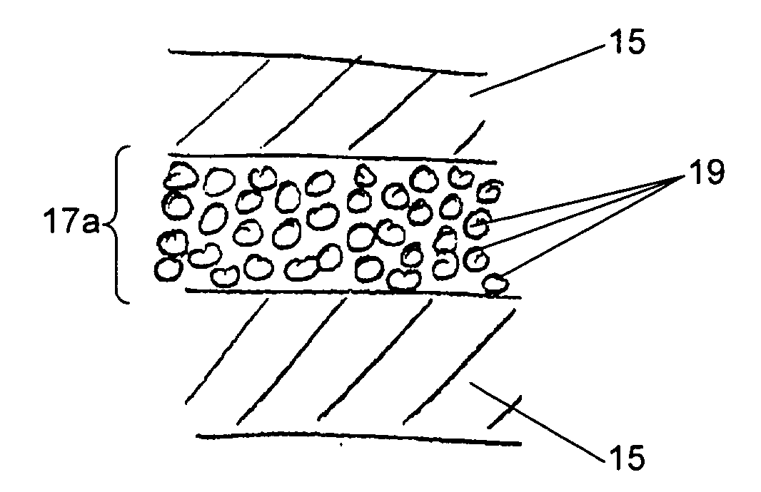
[0014]One aspect of certain example embodiments relates to replacing at least some of the material in “lead-free” frits with material that has reduced, or no, impact on strength. In this regard, certain example embodiments relate to frits or solder glass material that includes beads (e.g., ceramic beads with solid or evacuated cores), which advantageously replace this material (which may include, for example Bismuth). In such embodiments, the beads may also reduce the bulk conductivity (e.g., bulk thermal conductivity) of the frit. The size and shape of the beads may be selected to have an increased “fill,” resulting in more volume and less impact on strength.

Problems solved by technology

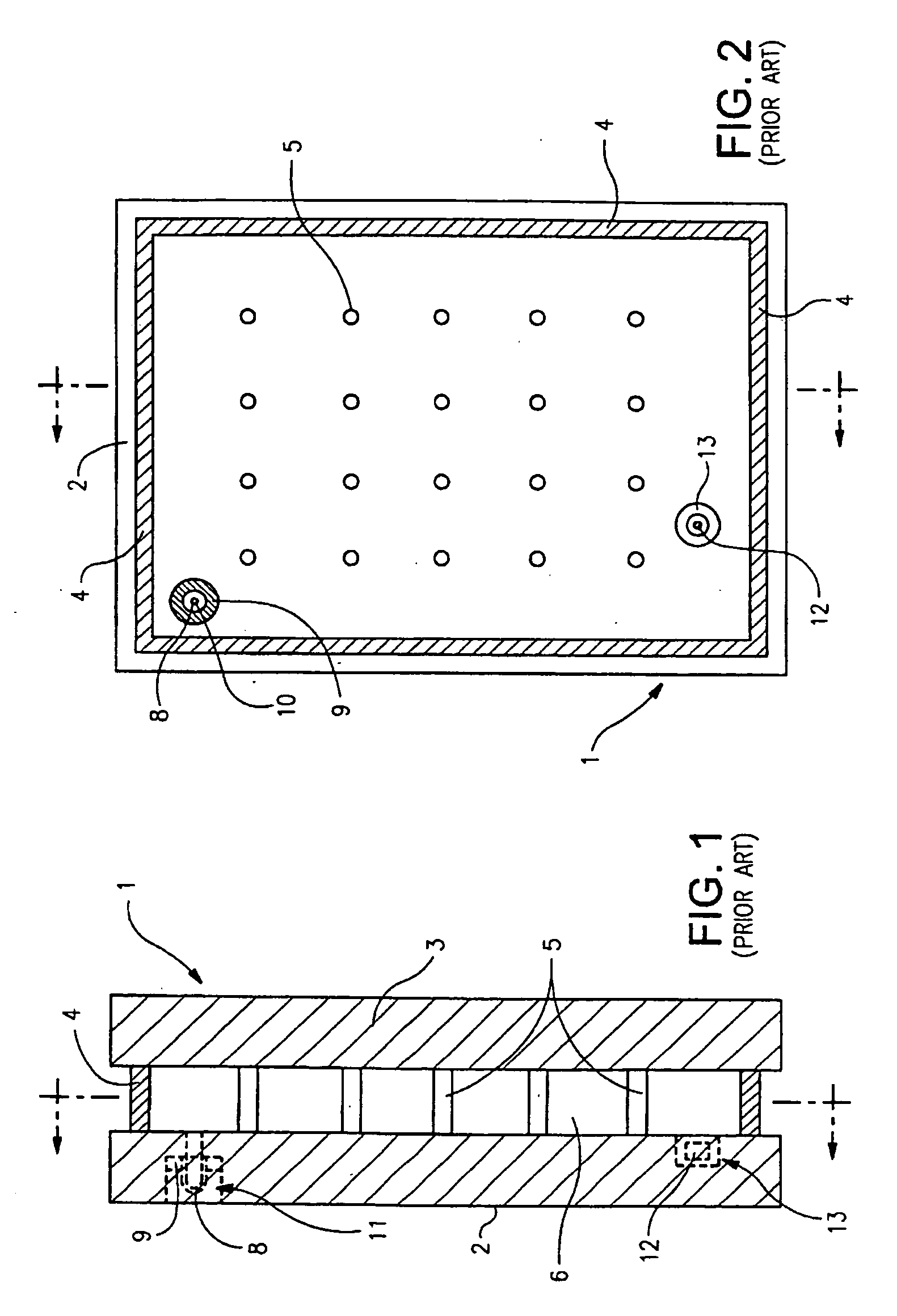
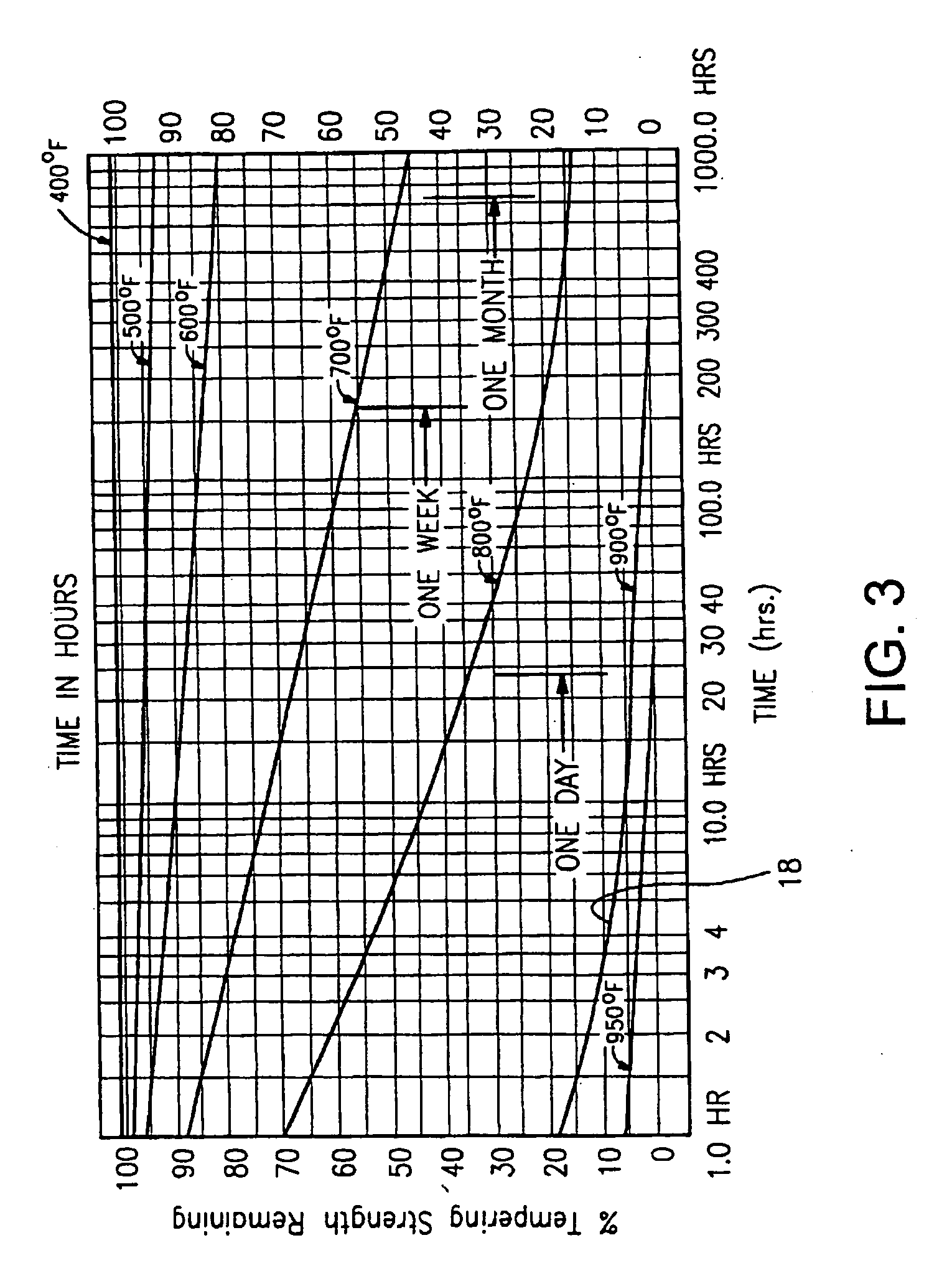
100061 Unfortunately, the aforesaid high temperatures and long heating times of the entire assembly utilized in the formulation of edge seal 4 are undesirable, especially when it is desired to use a heat strengthened or tempered glass substrate(s) 2, 3 in the vacuum IG unit.
Moreover, such high processing temperatures may adversely affect certain low-E coating(s) that may be applied to one or both of the glass substrates in certain instances.
Such a significant loss (i.e., 80% loss) of temper strength is of course undesirable.
This may or may not be desirable in some instances.
Even when non-tempered glass substrates are used, the high temperatures applied to the entire VIG assembly may soften the glass or introduce stresses, and partial heating may introduce more stress.
These stresses may increase the likelihood of deformation of the glass and / or breakage.
Moreover, the ceramic or solder glass edge seals of conventional VIG units tend to be brittle and prone to cracking and / or breakage, reducing the ability of individual glass panels to move relative to one another.
Although there are some commercially available “lead-free” frits that begin to address environmental and safety concerns, such frit material tends to be much more expensive than conventional leaded frit material.
In such embodiments, the beads may also reduce the bulk conductivity (e.g., bulk thermal conductivity) of the frit.

Method used


Image

  • Frit or solder glass compound including beads, and assemblies incorporating the same
  • Frit or solder glass compound including beads, and assemblies incorporating the same
  • Frit or solder glass compound including beads, and assemblies incorporating the same

Examples


Embodiment Construction

[0028]Certain example embodiments of this invention relate to frits or solder glass compounds that include beads, and / or assemblies such as, for example, vacuum insulated glass (VIG) units or plasma display panels (PDPs) including the same. In certain example embodiments, the beads may be hollow glass beads of any suitable shape (e.g., substantially spherical, substantially eye shaped, substantially oblong, substantially square shaped, etc.) with or without evacuated cavities. In certain example embodiments, hollow or solid beads may be added to a wet frit slurry, ink, or paint for use in plasma display panels (PDPs), vacuum insulated glass (VIG) units, or other assemblies. In certain example embodiments, the beads may be hollow glass beads of any suitable shape (e.g., substantially spherical, substantially eye shaped, substantially oblong, substantially square shaped, etc.) with hollow (and sometimes evacuated) or solid cavities. The wet frit slurry, ink, or paint with the beads of...


PUM

PropertyMeasurementUnit
temperatureaaaaaaaaaa

Abstract

Certain example embodiments of this invention relate to frits or solder glass compounds that include beads, and / or assemblies such as, for example, vacuum insulated glass (VIG) units or plasma display panels (PDPs) including the same. In certain example embodiments, the beads may be hollow glass beads of any suitable shape (e.g., substantially spherical, substantially eye shaped, substantially oblong, substantially square shaped, etc.) with or without evacuated cavities. The inclusion of such beads in a frit material may improve the thermal properties of the bulk fired frit in certain example instances. Additionally, the inclusion of such beads in a frit material may take the place of other more expensive materials in the frit, thereby reducing the costs associated with the fabrication of the assemblies.

Description

FIELD OF THE INVENTION[0001]Certain example embodiments of this invention relate to frits or solder glass compounds for use assemblies. More particularly, certain example embodiments of this invention relate to frits or solder glass compounds that include beads, and / or assemblies such as, for example, vacuum insulated glass (VIG) units or plasma display panels (PDPs) including the same. In certain example embodiments, the beads may be hollow glass beads of any suitable shape (e.g., substantially spherical, substantially eye shaped, substantially oblong, substantially square shaped, etc.) with or without evacuated cavities. The inclusion of such beads in a frit material may improve the thermal properties of the bulk fired frit in certain example instances. Additionally, the inclusion of such beads in a frit material may take the place of other more expensive materials in the frit, thereby reducing the costs associated with the fabrication of the assemblies.BACKGROUND AND SUMMARY OF E...

Claims


Application Information

Patent Timeline
Patent Type & Authority Applications(United States)
IPC IPC(8): C03C8/02B32B17/00E06B3/26B32B17/06C03C27/04
CPCC03C8/02C03C8/14C03C8/24Y10T428/252E06B3/6612E06B2003/66338Y02B80/24C03C27/06Y02B80/22Y02A30/249
Inventor COOPER, DAVID J.
Owner GUARDIAN GLASS LLC
Learn More