
Fuel reformers utilizing taylor vortex flows

a technology of fuel reformers and vortex flows, which is applied in the direction of liquid-gas reaction processes, metal/metal-oxide/metal-hydroxide catalysts, chemical processes cannot tolerate even minute amounts, and sulphur or its compounds become additional contaminants. it can facilitate the removal of contaminants and promote the increase of reformer reaction rates

Active Publication Date: 2010-12-30
GLOBAL ENERGY SCI CALIFORNIA
View PDF7 Cites 12 Cited by
  • Summary
  • Abstract
  • Description
  • Claims
  • Application Information

AI Technical Summary

Benefits of technology

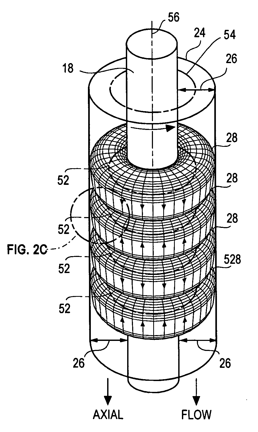
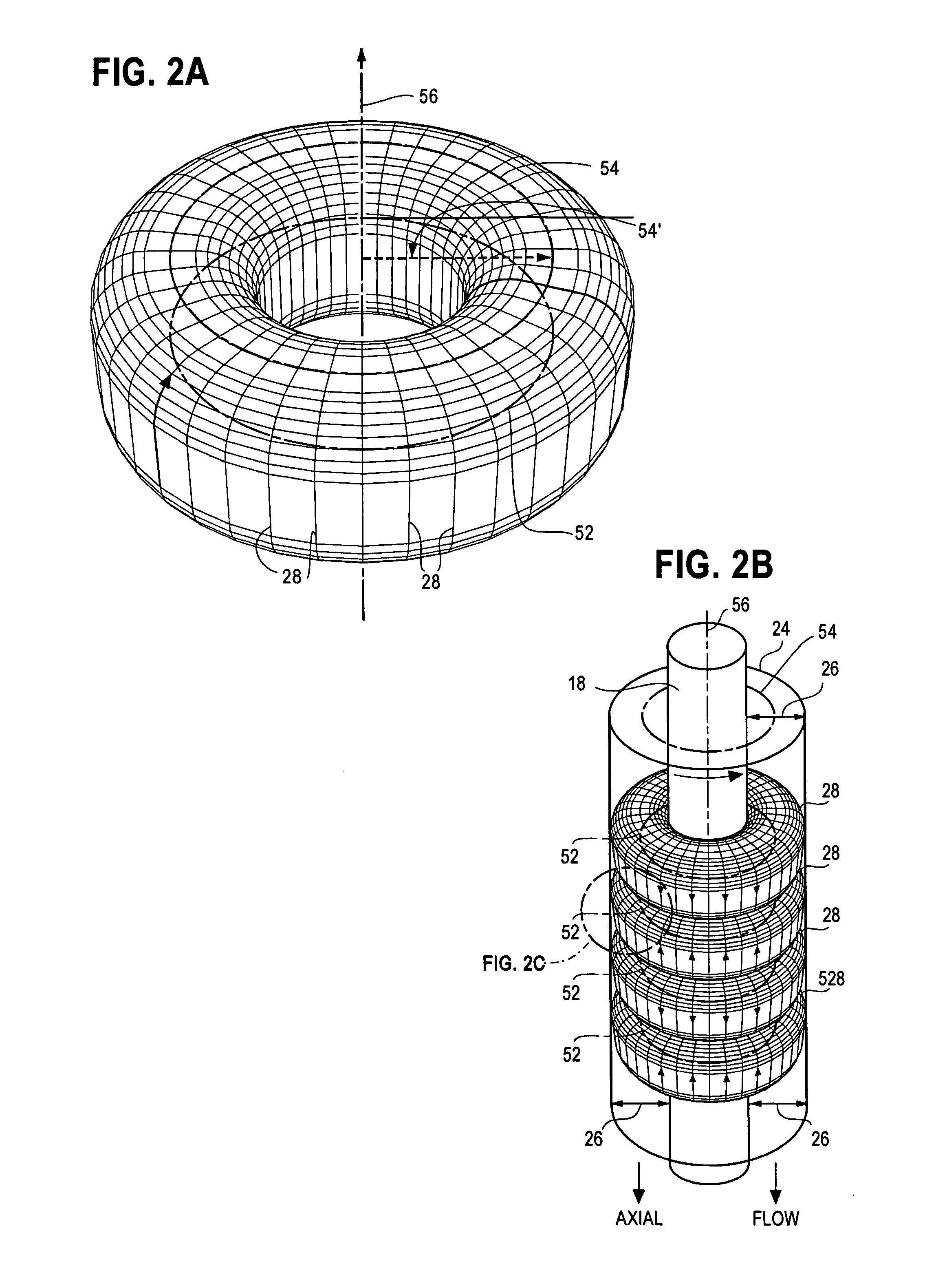
[0021]This invention uses Taylor Vortex Flows (“TVF”—also known as Taylor—Couette Flows) in fuel reformers to achieve enhanced reaction rates and product extraction efficiencies by a) accelerating mass transport of reactants at catalyst surfaces, b) simultaneously and rapidly removing target reaction products from the reaction, c) preventing strong carbon adhesion to catalyst surfaces, d) capturing reaction contaminants that can degrade both catalyst and filtering surfaces and e) eliminating those degrading reaction products from the reformers.
[0031]The present invention is a robust fuel reformer in which fuel passes between relatively rotating, cylindrical surfaces that cause Taylor Vortex Flows (TVF) and Circular Couette Flows (CCF) within the fuel. TVF facilitates removal of contaminants that could damage the reformers or fuel cells and chemical reactors that use hydrogen produced by the reformers.
[0032]It is therefore a first object this invention to provide a robust fuel reformer and method for converting a hydrogen-containing fuel into separable H2 through the use of TVF that capture and eliminate reaction byproducts and contaminants.
[0035]A fourth object of this invention is to provide structure for a fuel reformer that will optimize its performance for extracting H2 from a fuel and separating H2 for removal and further use.

Problems solved by technology

Where fuel contains sulphur (S), sulphur or its compounds also become additional contaminants.
Even where sulphur contaminants are present in low concentrations, they can foul or destroy catalysts and other components in chemical reactors.
Some fuel cells chemical processes cannot tolerate even minute amounts of carbon, carbon monoxide, carbon dioxide or sulphur oxides so their reformers require external purifiers that add cost and complexity to the reformers.

Method used


Image

  • Fuel reformers utilizing taylor vortex flows
  • Fuel reformers utilizing taylor vortex flows
  • Fuel reformers utilizing taylor vortex flows

Examples


Embodiment Construction

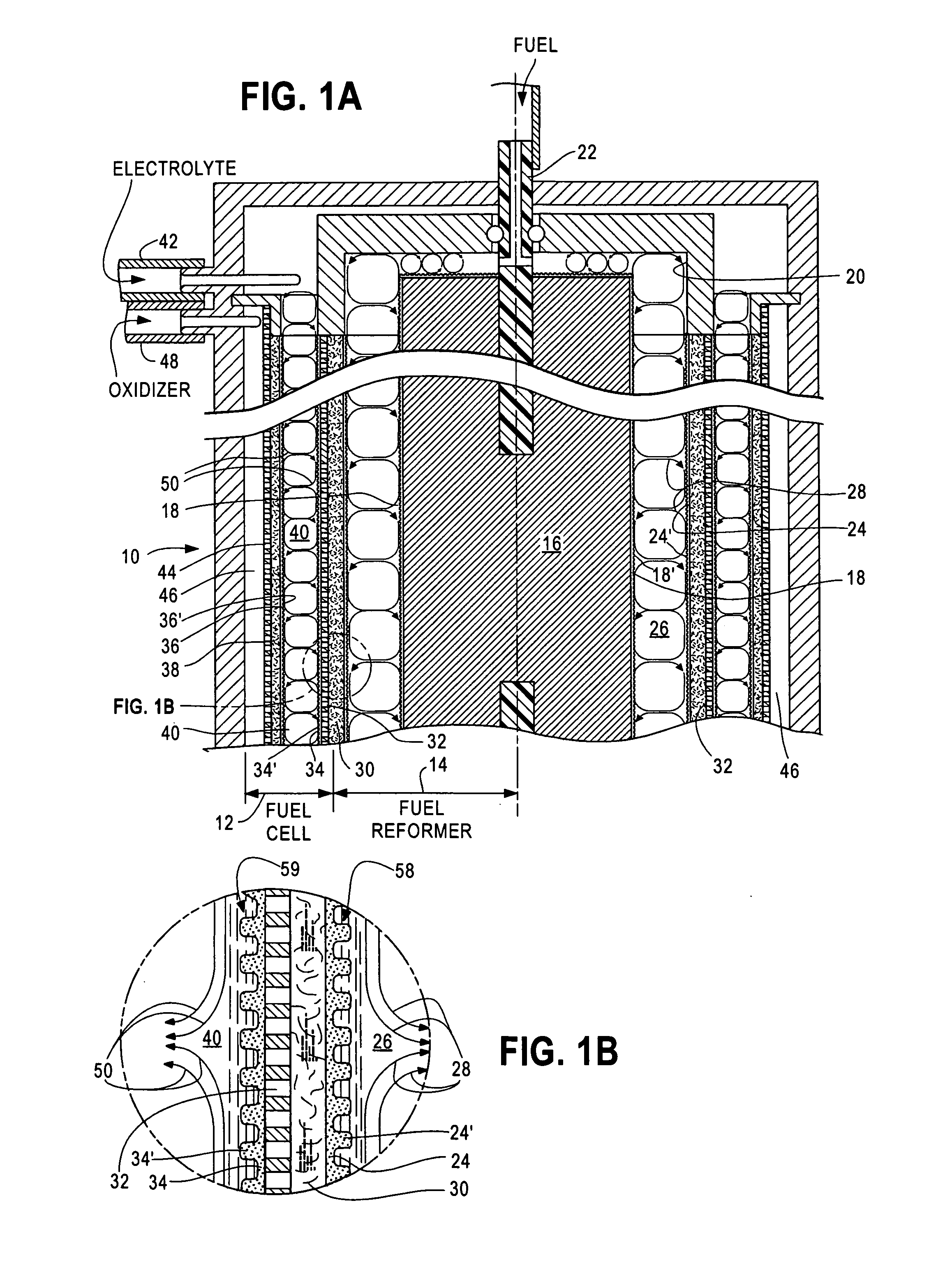
[0048]FIG. 1A is a cross-sectional view of essential features of a preferred embodiment of an electrochemical cell 10 of this invention, as taught in Case A, cited above. The electrochemical cell 10 is configured as a combination fuel cell 12 and fuel reformer 14 that performs direct internal reforming (DIR).

[0049]The reformer 14 portion extracts H2 gas from fuels, such as methane mixed with steam. The H2 gas is subsequently used for powering the fuel cell 12 portion that converts H2 and O2 gases into electrical energy and water. Extraction of H2 in such an electrochemical cell 10 is known as direct internal reforming of fuel.

[0050]Reformer 14 comprises a fixed cylinder 16 having a porous reformer inner catalytic shell 18 on its impervious outer wall. Cylinder 16 is fixed to the frame of cell 10 by means not shown. Cylinder 16 may contain a heater (not shown) for providing thermal energy to the reformer's 14 endothermic fuel reforming chemical reaction. More commonly, heat is provid...


PUM

PropertyMeasurementUnit
Timeaaaaaaaaaa
Lengthaaaaaaaaaa
Lengthaaaaaaaaaa

Abstract

Steam, partial oxidation and pyrolytic fuel reformers (14 or 90) with rotating cylindrical surfaces (18, 24 or 92, 96) that generate Taylor Vortex Flows (28 or 98) and Circular Couette Flows (58, 99) for extracting hydrogen from hydrocarbon fuels such as methane (CH4), methanol (CH3OH), ethanol (C2H5OH), propane (C3H8), butane (C4H10), octane (C8H18), kerosene (C12H26) and gasoline and hydrogen-containing fuels such as ammonia (NH3) and sodium borohydride (NaBH4) are disclosed.

Description

CROSS-REFERENCE TO RELATED APPLICATIONS[0001]This application claims the benefit of my U.S. Provisional Application No. 61 / 220,583 filed 26 Jun. 2009, which is incorporated herein by reference.[0002]This application, identified as Case B, is related to my following applications:[0003]Case A: Electrochemical Cells Utilizing Taylor Vortex Flows, application Ser. No. ______;[0004]Case C: Chemical Process Accelerator Systems Utilizing Taylor Vortex Flows, application Ser. No. ______;[0005]Case D: Direct Reaction Fuel Cells Utilizing Taylor Vortex Flows, application Ser. No. ______; and[0006]Case E: Dynamic Accelerated Reaction Batteries Utilizing Taylor Vortex Flows, filed application Ser. No. ______ with Philip Michael Lubin and Daniel Timothy Lubin.Case A, Case B (this case), Case C, Case D and Case E were all filed on the same day. All of these applications have been assigned to the same assignee. The other applications are incorporated herein by reference.STATEMENT REGARDING FEDERAL...

Claims


Application Information

Patent Timeline
IPC IPC(8): H01M8/06B01J8/14B01J8/00
CPCB01F7/008Y02E60/522B01J12/007B01J14/005B01J15/005B01J16/005B01J19/1806B01J19/1893B01J2219/00083B01J2219/00135C01B3/065C01B3/40C01B2203/0233C01B2203/0261C01B2203/0277C01B2203/0283C01B2203/066C01B2203/1041C01B2203/1047C01B2203/1064C01B2203/107C01B2203/1076C01B2203/1082C01B2203/1223C01B2203/1229C01B2203/1241C01B2203/1247H01M4/90H01M4/92Y02E60/362Y02E60/523Y02E60/50B01J10/007Y02P20/52Y02E60/36B01F27/272
Inventor FISCHEL, HALBERT
Owner GLOBAL ENERGY SCI CALIFORNIA
Learn More