
Ultrasound diagnosis apparatus and method of setting sound velocity

Active Publication Date: 2010-12-30
TOSHIBA MEDICAL SYST CORP
View PDF8 Cites 17 Cited by
  • Summary
  • Abstract
  • Description
  • Claims
  • Application Information

AI Technical Summary

Benefits of technology

[0031]Exemplary embodiments of an ultrasound diagnosis apparatus and a method of setting sound velocity will be explained below in detail with reference to the accompanying drawings. An ultrasound diagnosis apparatus that executes a method of setting sound velocity is explained below as the embodiments.

Problems solved by technology

However, according to such technologies, there are constraints that a reflective body, such as a calculus or a boundary wall, needs to be present in a detection area of a living-body sound velocity, and furthermore, a reflective body has to be a point, consequently, such technologies cannot be generally used.
However, according to the conventional technologies described above, although an optimal sound velocity in a particular area is determined with objective numerical values (contrast values); when the calculation precision of the contrast values is insufficient, there is a case where the lateral resolution of a portion to be focused by an engineer who takes an ultrasound image or an image reader who reads an ultrasound image does not always become optimal, even if the ultrasound image is created by the determined optimal sound velocity.

Method used


Image

  • Ultrasound diagnosis apparatus and method of setting sound velocity
  • Ultrasound diagnosis apparatus and method of setting sound velocity
  • Ultrasound diagnosis apparatus and method of setting sound velocity

Examples


first embodiment

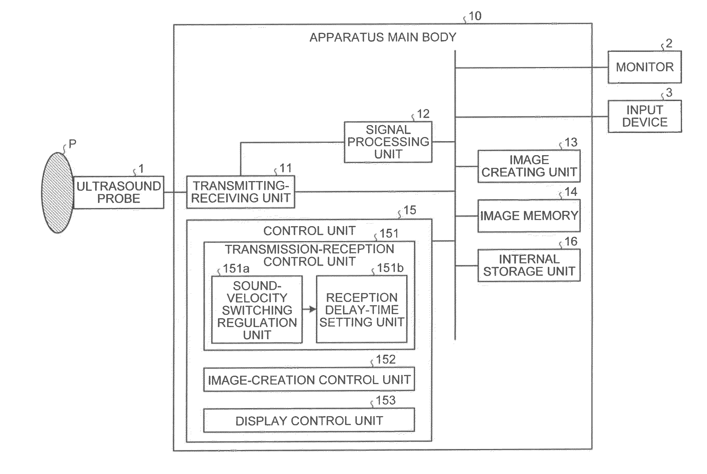
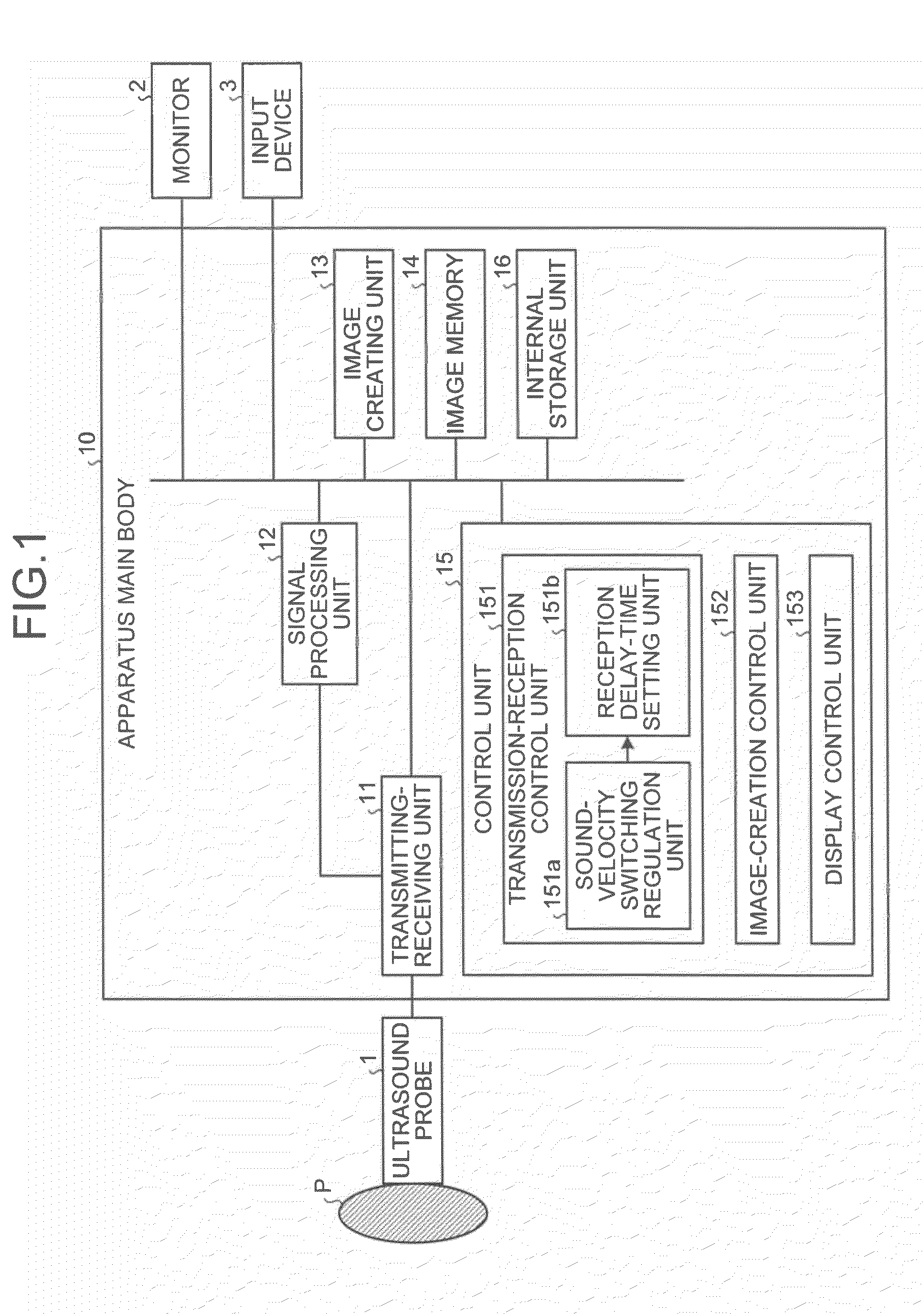
[0032]First of all, a configuration of an ultrasound diagnosis apparatus according to an embodiment is explained below. FIG. 1 is a schematic diagram for explaining a configuration of an ultrasound diagnosis apparatus according to a As shown in FIG. 1, the ultrasound diagnosis apparatus according to the embodiment includes an ultrasound probe 1, a monitor 2, an input device 3, and an apparatus main body 10.

[0033]The ultrasound probe 1 includes a plurality of piezoelectric vibrators of an electronic scan type that are arranged on a row. The piezoelectric vibrators generate ultrasound waves based on a driving signal supplied from a transmitting-receiving unit 11 included in the apparatus main body 10, which will be described later. Furthermore, the piezoelectric vibrators receive a reflected wave from a subject P, and convert it into an electric signal. Moreover, the ultrasound probe 1 includes a conformation layer provided to the piezoelectric vibrators, and a backing material that ...

second embodiment

[0096]Accordingly, the processing by the transmission-reception control unit 151, the image-creation control unit 152, and the display control unit 153 is again started. However, the sound-velocity switching regulation unit 151a regulates switching of the set sound velocity after regulating so as to include the optimal sound velocities determined by the optimal sound-velocity determining unit 154 in the switching route.

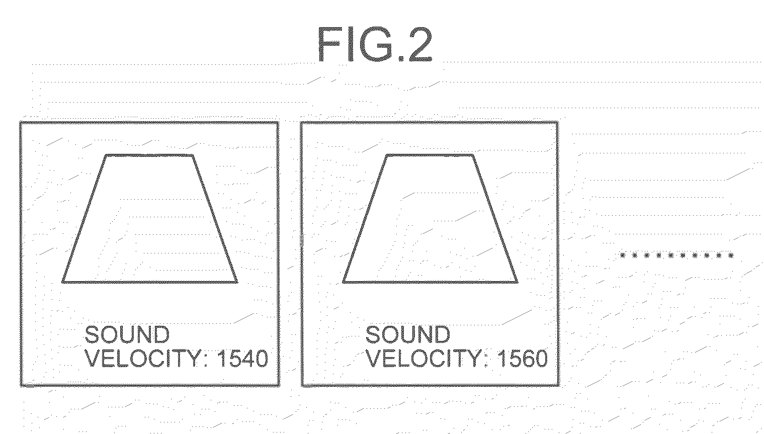
[0097]For example, as shown in FIG. 9, similarly to the first embodiment, assuming that the set sound velocity at the present moment is “1540 m / sec”, and a variable range of the set sound velocity is “from 1400 m / sec to 1600 m / sec”; when the sound-velocity switching button is pressed, the sound-velocity switching regulation unit 151a regulates switching of the set sound velocity based on that time-intervals of switching the sound velocity are regular, and value-intervals of switching the sound velocity value are constant (interval 20 m / sec in the figure).

[0098]In oth...

third embodiment

[0124]Precisely, as shown in FIG. 11, in the ultrasound diagnosis apparatus when a request for image display is received from the operator via the input device 3 (Yes at Step S401); the monitor 2 displays ultrasound images sequentially read from the image memory 14, in cine display, by the control by the display control unit 153 (Step S402).

[0125]The image-creation control unit 152 then determines whether ultrasound image is selected as the freeze button of the input device 3 is pressed by the operator who refers to ultrasound images displayed in cine display on the monitor 2 (Step S403).

[0126]If ultrasound image is not selected (No at Step S403); the display control unit 153 controls display such that the cine display is continued on the monitor 2 (Step S404); and the image-creation control unit 152 continues determination processing at Step S403.

[0127]By contrast, if an ultrasound image is selected (Yes at Step S403); the image-creation control unit 152 controls the reception del...


PUM


Abstract

In one embodiment, an ultrasonic diagnostic apparatus includes an image creating unit, an image-creation control unit and a display control unit. The image creating unit creates an ultrasound image from data created by adding a reflected wave signal of an ultrasound wave transmitted to an imaging target portion of a subject by using a reception delay time calculated from a set sound velocity set as a sound velocity in the imaging target portion. The image-creation control unit switches a set sound velocity set at a present moment in a variable range, and controls the image creating unit so as to create a plurality of ultrasound images each using a reception delay time corresponding to each of the set sound velocities to be switched. The display control unit controls display such that the ultrasound images created are displayed on a certain display unit.

Description

CROSS-REFERENCE TO RELATED APPLICATIONS[0001]This application is based upon and claims the benefit of priority from Japanese Patent Application No. 2009-155477, filed on Jun. 30, 2009 and Japanese Patent Application No. 2010-116259, filed on May 20, 2010; the entire contents of all of which are incorporated herein by reference.FIELD[0002]Embodiments described herein relate generally to an ultrasound diagnosis apparatus and a method of setting sound velocity.BACKGROUND[0003]Conventionally, an ultrasound diagnosis apparatus employs a method of focusing a transmission beam and a reception beam of ultrasound waves in order to increase a lateral resolution of an ultrasound image. Particularly, an ultrasound diagnosis apparatus using an ultrasound probe including an array vibrator of an electronic scan type uses an electronic focusing method of adding reception signals of respective channels by delay-time control.[0004]However, according to the electronic focusing method, a reception beam...

Claims


Application Information

Patent Timeline
IPC IPC(8): A61B8/14
CPCA61B8/06A61B8/54G01S7/52074G01S7/52073G01S7/52049
Inventor KAKEE, AKIHIROKATAGUCHI, MUNEKIICHIOKA, KENICHIKAMEWADA, YASUSHI
Owner TOSHIBA MEDICAL SYST CORP
Learn More