
Orthopaedic implant and fastener assembly

a technology for orthopaedic implants and screws, which is applied in the field of intramedullary nail or plate and screw assembly, can solve the problems of femoral head compression, screw sliding through the nail, excessive compression of the femoral head, etc., and achieves the effect of reducing the mass in the cross section, increasing the strength and resistance to tension, and adding additional mass in the lateral portions

Active Publication Date: 2010-12-30
SMITH & NEPHEW INC
View PDF21 Cites 20 Cited by
  • Summary
  • Abstract
  • Description
  • Claims
  • Application Information

AI Technical Summary

Benefits of technology

[0009]Fastening assemblies of methods, devices and systems according to certain embodiments of the invention preferably include an engaging member and a compression device. The fastening assemblies are adapted to be received in the transverse aperture of the implant in a sliding relationship, so that the fastening assembly is adapted to slide with respect to the transverse aperture, and thus apply compression to a fracture and for any other desired purpose. The engaging member is adapted to gain purchase in a second bone fragment. The engaging member and the compression device are configured so that the compression device interacts with a portion of the implant and also with a portion of the engaging member so that adjustment of the compression device controls sliding of the engaging member relative to the implant and thereby enables controlled movement between the first and second bone fragments. In some embodiments, the compression device at least partially directly contacts the second bone fragment when implanted.

Problems solved by technology

When an additional screw or pin is used, however, unequal forces applied to the separated screws or pins can cause the separate screws or pins to be pressed against the sides of the holes through which the separate screws or pins are intended to slide.
This may result in binding, which reduces the sliding of the screws or pins through the nail.
Conversely, a problem can result from excessive compression of the femoral head toward or into the fracture site.
In extreme cases, excessive sliding compression may cause the femoral head to be compressed all the way into the trochanteric region of the femur.
Furthermore, overly rigid nails sometimes generate periprosthetic fractures in regions away from a fracture site.
Intramedullary nails of the prior art, however, are usually round or square in cross-section, and therefore not anatomically consistent with the cortical bone or the medullary canal.
This approach, however, can remove significant portions of healthy cortical bone.
However, none of these hip stems have been incorporated into a nail or configured to accept a screw or screws useful in repairing substantially all of the portions of the treated bone.

Method used


Image

  • Orthopaedic implant and fastener assembly
  • Orthopaedic implant and fastener assembly
  • Orthopaedic implant and fastener assembly

Examples


Embodiment Construction

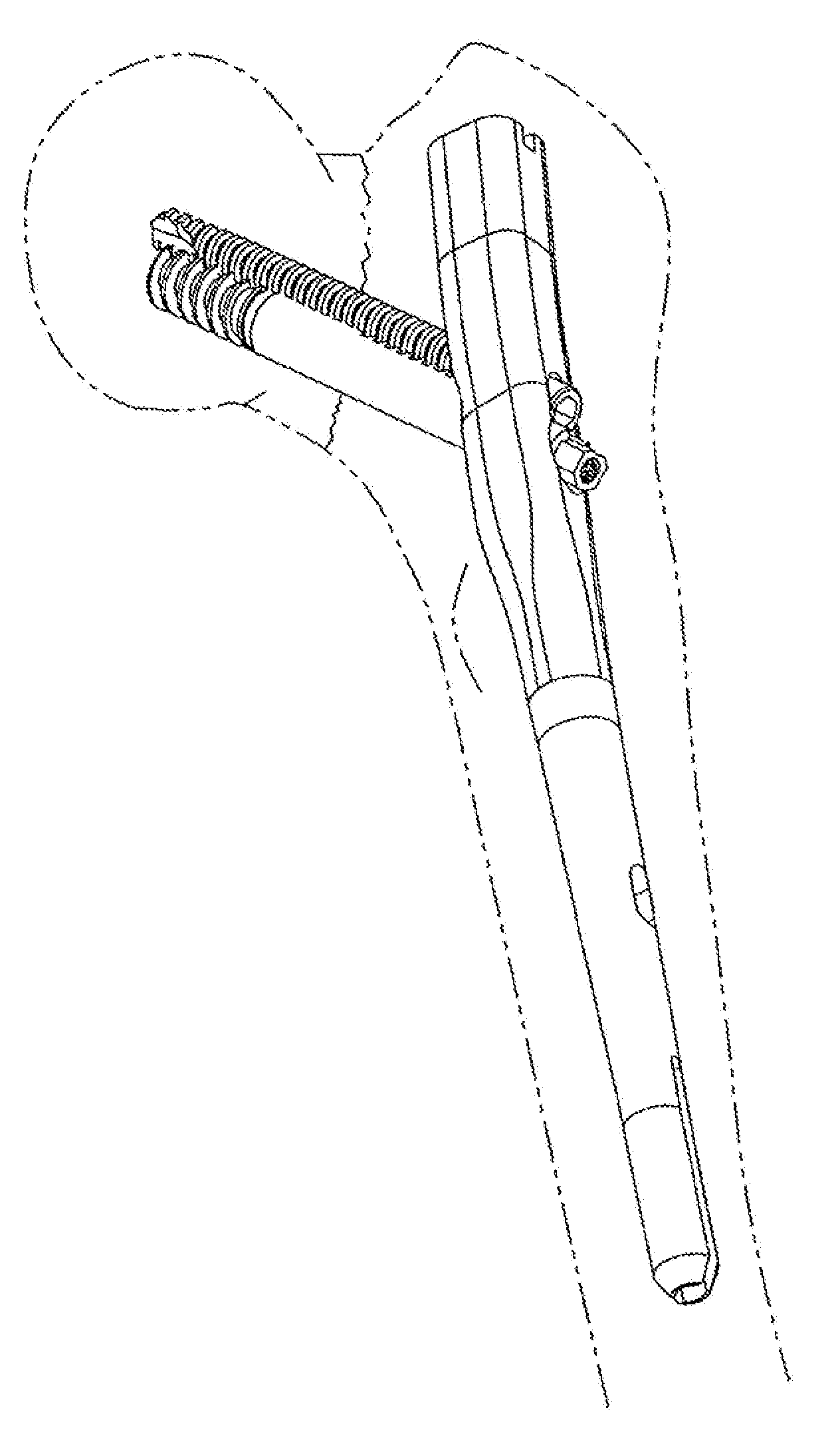
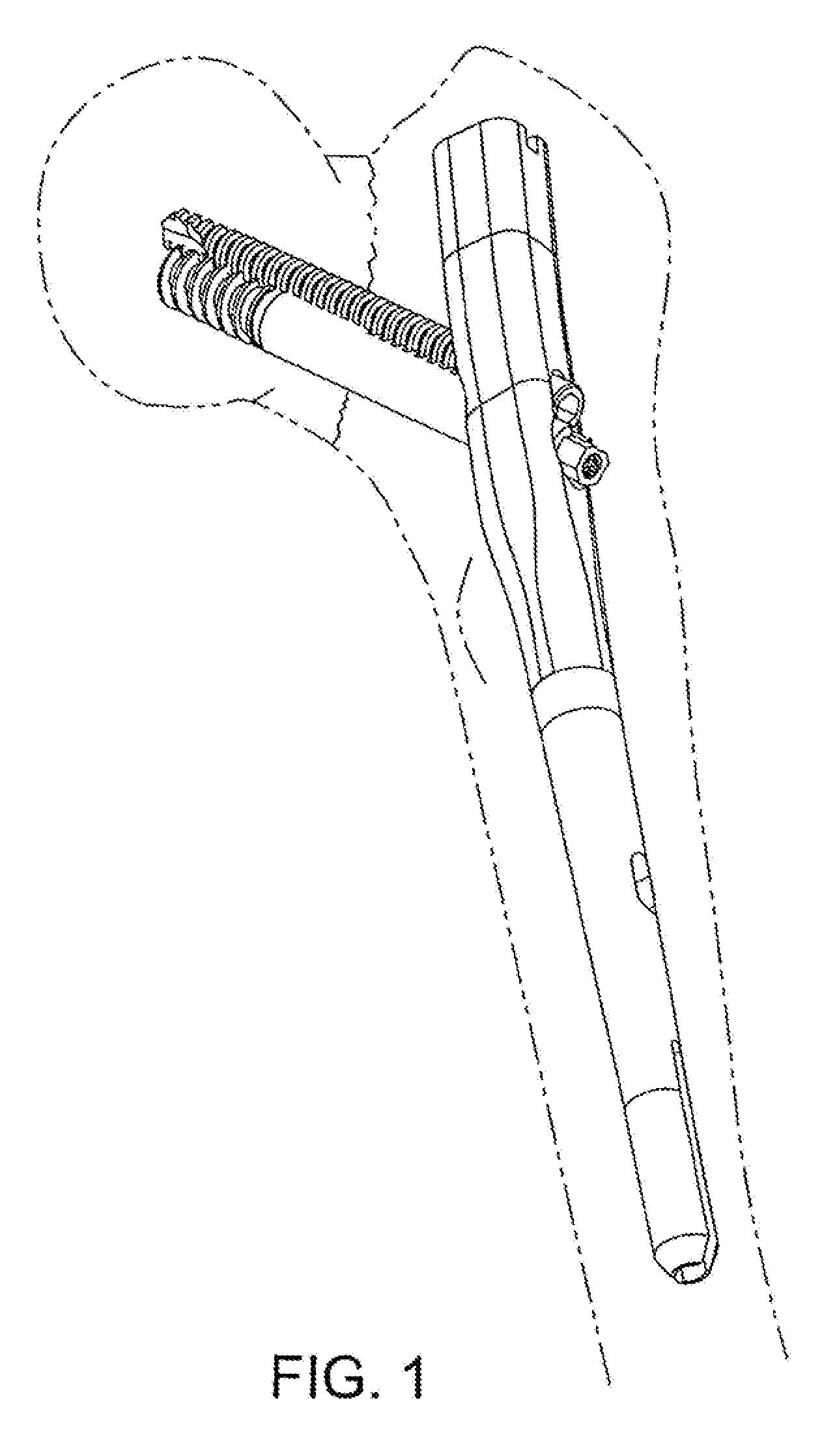
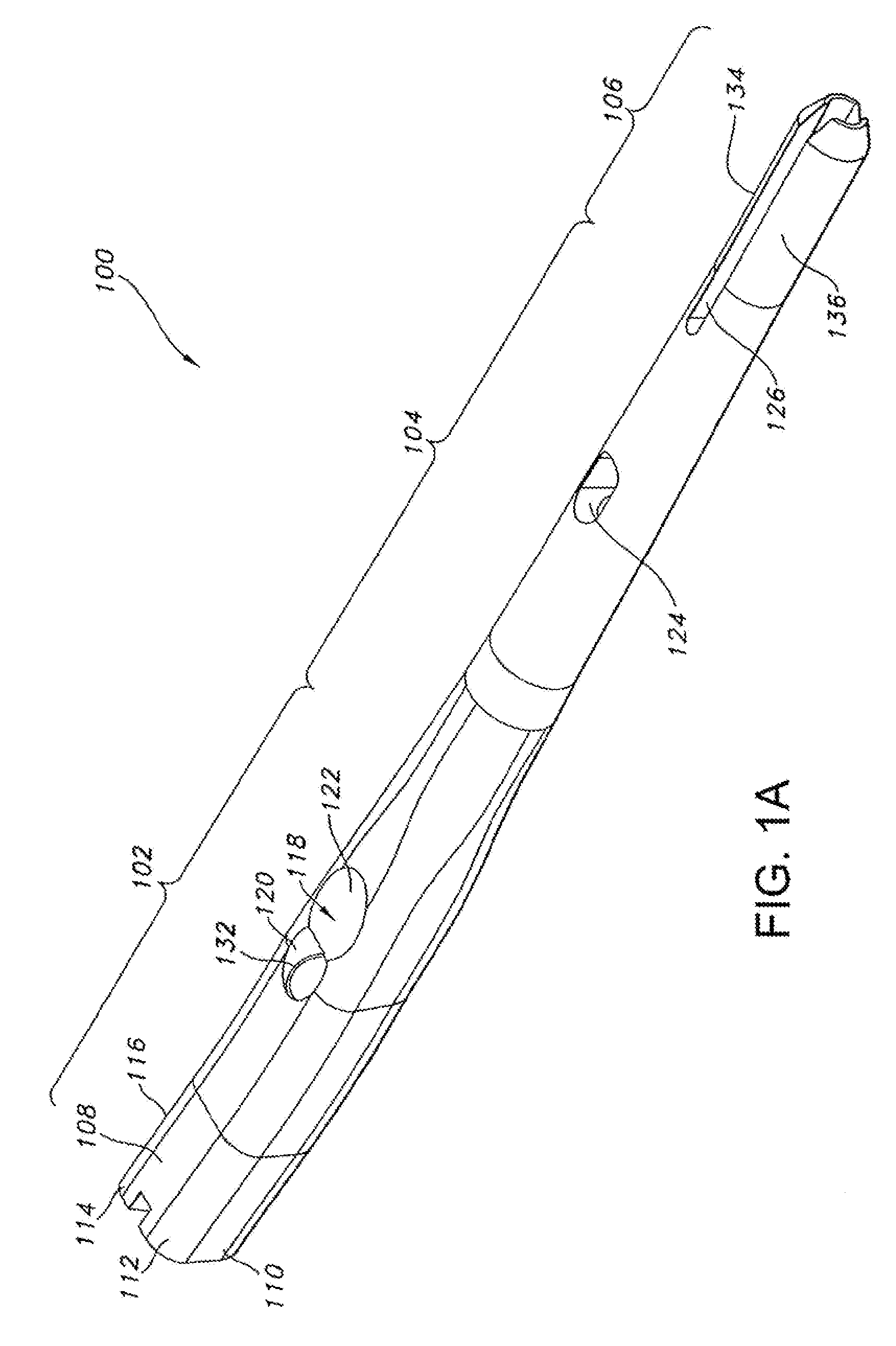
[0065]Methods, devices and systems according to embodiments of this invention seek to provide improved treatment of femur fractures. FIGS. 1-6 illustrate various views of one embodiment of an intramedullary nail 100 of the present invention. The intramedullary nail 100 has a longitudinal bore 130 throughout to aid in insertion in the bone. The intramedullary nail 100 has a proximal section 102, a transition section 104 and a distal section 106.

[0066]The proximal section 102 of the particular structure shown in FIGS. 1-6 preferably features an anatomically inspired shape that corresponds more accurately to typical cortical bone. One version of such shape is shown in the cross-sectional view of the proximal section 102 in FIG. 6. The particular cross-section of the proximal section 102 shown in FIG. 6 is generally non-circular along at least some portions of its length, and has a lateral side or aspect 108 that is larger than a medial side or aspect 109. The lateral side 108 and media...


PUM


Abstract

Treating fractures using one or both of an implant, such as an intramedullary nail, and a fastening assembly, such as a lag screw and compression screw assembly. The implant in some embodiments has a proximal section with a transverse aperture having a non-circular cross-section that may be shaped to selectively constrain the fastening assembly within the transverse aperture. Two or more components of the fastening assembly may be received to slide, in a controlled way, in the transverse aperture of the implant, and to cooperate to resist a force moment applied thereto. Without the presence of one of the components, such as the lag screw, another component, such as the compression screw may not resist a force moment applied thereto. In some implementations, an engaging member and a compression device of the fastening assembly are configured so that the compression device interacts with a portion of the implant and a portion of the engaging member to enable controlled movement between first and second bone fragments. This configuration is useful for, among other things, compressing a fracture.

Description

FIELD OF THE INVENTION[0001]The present invention generally relates to a system for coupling bone portions across a fracture and, more specifically, to an intramedullary nail or plate and screw assembly used to treat fractures of long bones such as the femur, humerus and tibia, and various periarticular fractures of these and other bones.BACKGROUND OF THE INVENTION[0002]There are a variety of devices used to treat fractures of the femur, humerus, tibia, and other long bones. For example, fractures of the femoral neck, head, and intertrochanteric region have been successfully treated with a variety of compression screw assemblies, which include generally a compression plate having a barrel member, a lag screw and a compressing screw. Examples include the AMBI® and CLASSIC™ compression hip screw systems offered by Smith & Nephew, Inc. In such systems, the compression plate is secured to the exterior of the femur, and the barrel member is inserted in a predrilled hole in the direction ...

Claims


Application Information

Patent Timeline
Patent Type & Authority Applications(United States)
IPC IPC(8): A61B17/56
CPCA61B17/7225A61B17/7233A61B17/725A61B17/8061A61B17/7283A61B17/744A61B17/746A61B17/7266
Inventor GRUSIN, NATHANIEL KELLEY
Owner SMITH & NEPHEW INC
Learn More