Force sensor apparatus

a technology of force sensor and apparatus, which is applied in the field of force sensor, can solve the problems of high repeatability, high accuracy, and high reliability of the operation environment of force sensor, and achieve the effects of reducing the lateral movement of the actuator, ensuring repeatability, and high repeatability

Active Publication Date: 2011-01-06
HONEYWELL INT INC
View PDF33 Cites 19 Cited by
  • Summary
  • Abstract
  • Description
  • Claims
  • Application Information

AI Technical Summary

Benefits of technology

[0008]The aforementioned hole associated with the cap generally restricts lateral movement of the actuator to ensure that contact is made with the force sense element in a repeatable location, thereby enabling a highly repeatable signal. Preferably, the cap can be configured with a height greater than the diameter of the actuator. Alternatively, the cap can be designed to be shorter which still reduces lateral movement of the actuator.
[0009]A cover associated with an integrated flexible membrane can be mounted on the substrate in order to protect internal components associated with the force sensor apparatus from an external environment. Additionally, the membrane in the cover assists in retaining the actuator and can be arranged to provide a small “pre-load” to further ensure repeatability, enable accurate operation with small loads, and also reduce mechanical impact on the sense element which can otherwise occur during heavy force cycling.
[0010]A signal conditioner, electrically coupled to the force sense element, can also be mounted on the substrate. The signal conditioner can condition the output signal and generate a calibrated output corrected for the effects of temperature and force sensitivity and non-linearity over the operating range. The force sense element and the signal conditioner can be electrically connected via wirebonds either directly or connected through the substrate. The actuator, acting through the hole associated with the cap, provides fast response time and a uniform application of force to the sense element.
[0011]Such a force sensor apparatus associated with the cap, wirebonds, and the cover provides flexibility in package design, fast response time, repeatable signal, and highly reliable mechanical and electrical connections.

Problems solved by technology

The operational environments in which force sensors operate can be very demanding and typically require high accuracy, high repeatability, fast response time, and high reliability.

Method used


Image

  • Force sensor apparatus
  • Force sensor apparatus
  • Force sensor apparatus

Examples


Embodiment Construction

[0016]The particular values and configurations discussed in these non-limiting examples can be varied and are cited merely to illustrate at least one embodiment and are not intended to limit the scope thereof.

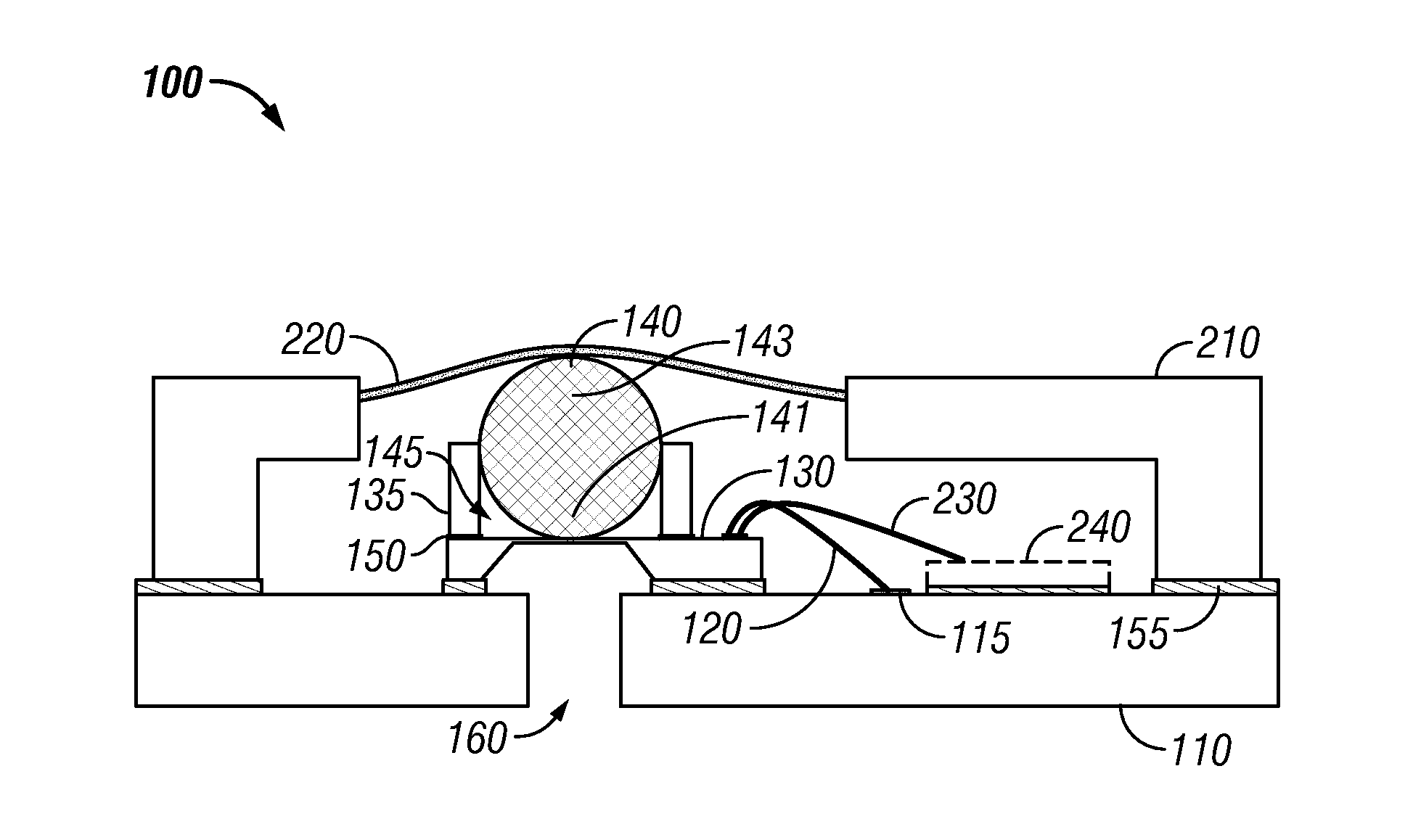
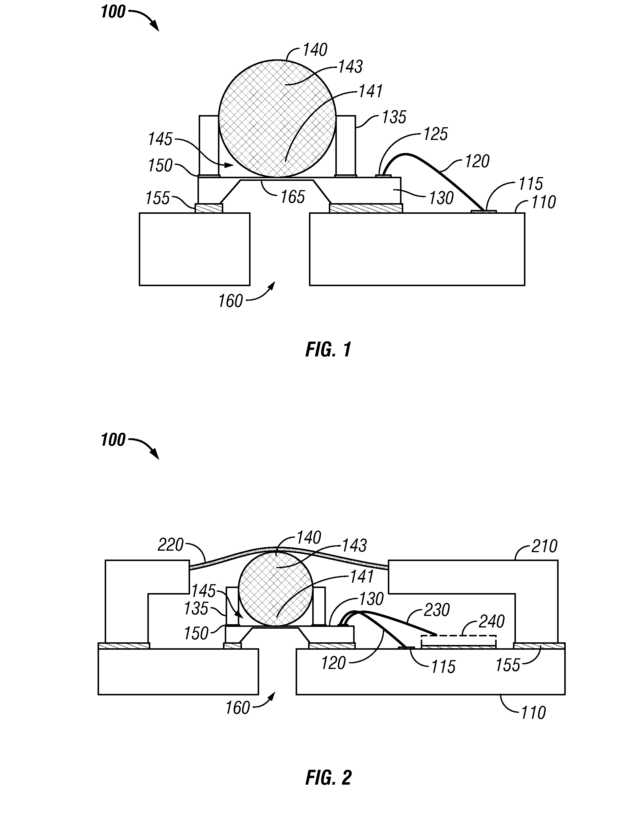
[0017]A force sensor can employ a force sense element, such as a piezoresistive silicon die, in combination with an actuator. The actuator can be arranged to press against the force sense element in response to an external force exerted against the actuator. The force sense element can include a flexible diaphragm which deflects in response to the actuator pressing on the force sense element. Deflection of the diaphragm may cause one or more piezoresistors disposed on or near the diaphragm to stress and change resistance. Electronic circuitry detects the change of resistance and determines the external force from the resistance change.

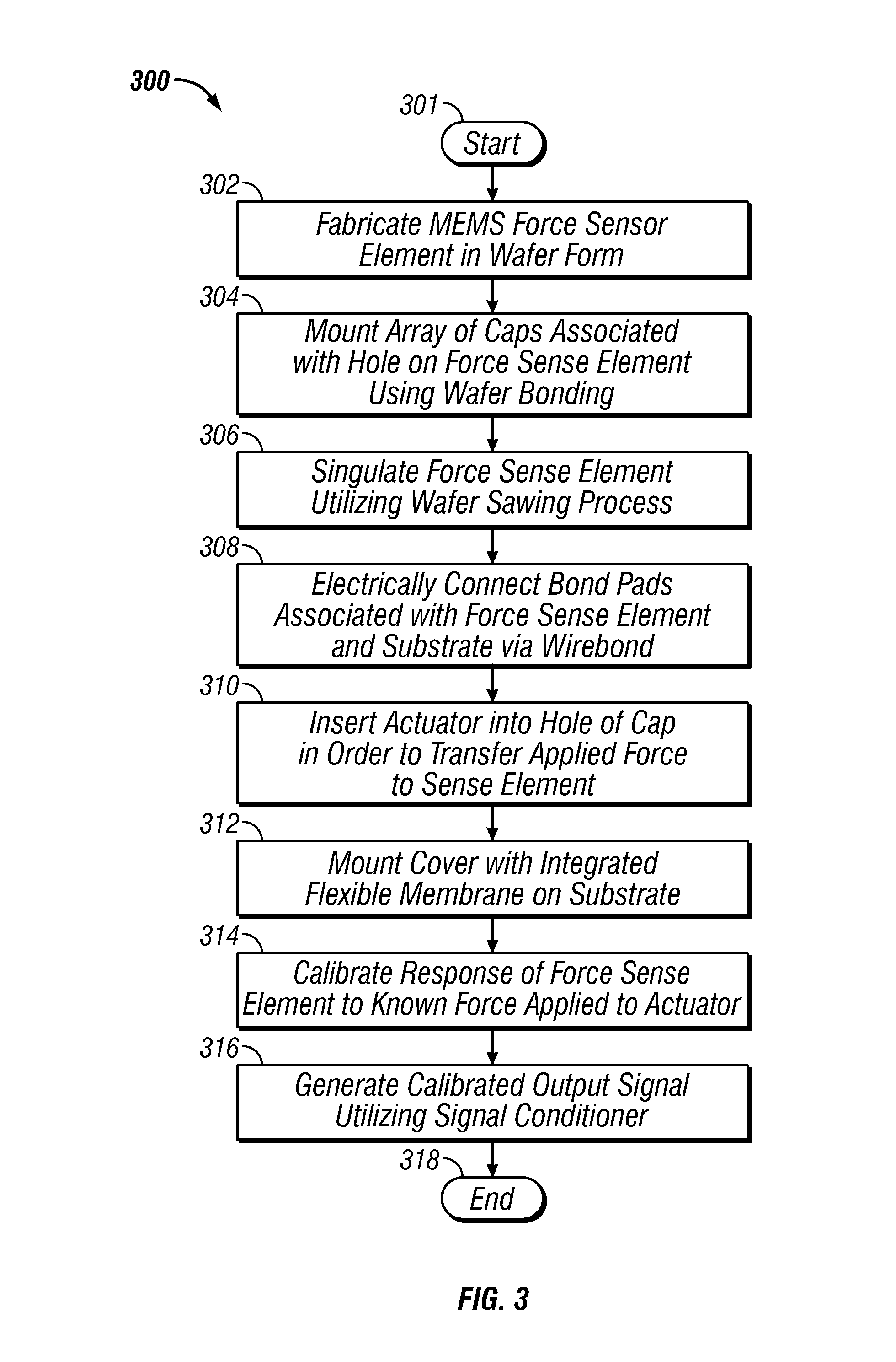
[0018]The disclosed embodiments generally involve singulated wafer portions. The use of such wafers and singulated wafer portions improves effici...


PUM

PropertyMeasurementUnit
sizeaaaaaaaaaa
sizeaaaaaaaaaa
sizeaaaaaaaaaa

Abstract

A force sensor apparatus and method of forming the same. The apparatus includes a force sense element that can be attached to a substrate. An actuator disposed in a hole formed within the cap is operably coupled to the force sense element for transferring force to the sense element in response to receiving a force from an external source. The force sense element is configured to sense the external force and generate an output signal representing the force. Preferably, one or more bond pads, associated with the force sense element and the substrate, can be electrically connected via wire bonding. A cover associated with an integrated flexible membrane can be mounted on the substrate in order to protect internal components associated with the force sensor apparatus from an external environment.

Description

TECHNICAL FIELD[0001]Embodiments are generally related to force sensors. Embodiments are also related to force sense elements for use with force sensors. Embodiments are additionally related to methods for packaging force sensors.BACKGROUND OF THE INVENTION[0002]A force sensor measures an external force applied to a sense element and generates an output signal representative of the applied force. Such force sensors are commonly utilized in a wide variety of applications such as, for example, automotive, aerospace, medical, industrial, and consumer applications. The operational environments in which force sensors operate can be very demanding and typically require high accuracy, high repeatability, fast response time, and high reliability. Such force sensors can be utilized for measuring a very low force with a reliable accuracy.BRIEF SUMMARY[0003]The following summary is provided to facilitate an understanding of some of the innovative features unique to the embodiments disclosed an...

Claims


Application Information

Patent Timeline
Patent Type & Authority Applications(United States)
IPC IPC(8): G01L1/00H01L21/50
CPCG01L1/18H01L2924/10253H01L2224/73265H01L2924/1461G01L1/2231H01L2224/48091H01L2924/00014H01L2924/00
Inventor BRADLEY, ALISTAIR DAVIDECKHARDT, TODDJONES, RYANWADE, RICHARD
Owner HONEYWELL INT INC
Why Eureka
Try Eureka