Air delivery unit

a technology of air delivery device and air delivery device, which is applied in the direction of lighting and heating apparatus, heating types, and mechanical/solid-state device details, etc., can solve the problems of high rigidity of the fan guard and is not easily deformed, so as to reduce the amount and speed of air, suppress the rise of the static pressure of the air delivery device, and reduce noise

Inactive Publication Date: 2011-01-06
DAIKIN IND LTD
View PDF10 Cites 9 Cited by
  • Summary
  • Abstract
  • Description
  • Claims
  • Application Information

AI Technical Summary

Benefits of technology

[0014]Accordingly, it is an objective of the present invention to provide an outdoor unit of an air conditioner that reduces the amount and the speed of air blown from an air blowing surface of a fan guard having a grill structure, suppresses rise of the static pressure of an air delivery device, and reduces noise caused by interference between bars of the fan guard grill and the air.

Problems solved by technology

Further, unlike conventional configurations, it is unnecessary to form a special passage configuration in the casing.
Further, since the fan guard is configured as the attachment frame with respect to the casing, the fan guard has high rigidity and is not easily deformed.

Method used


Image

  • Air delivery unit
  • Air delivery unit
  • Air delivery unit

Examples


first embodiment

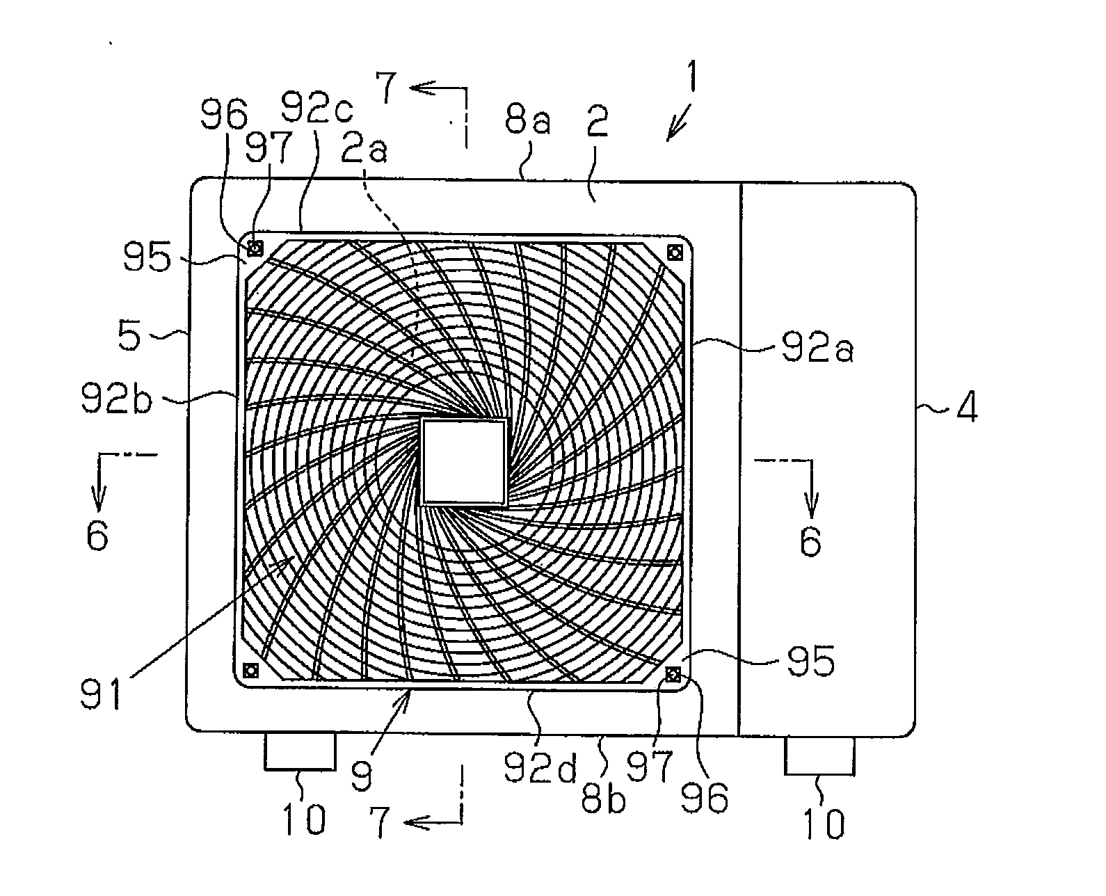
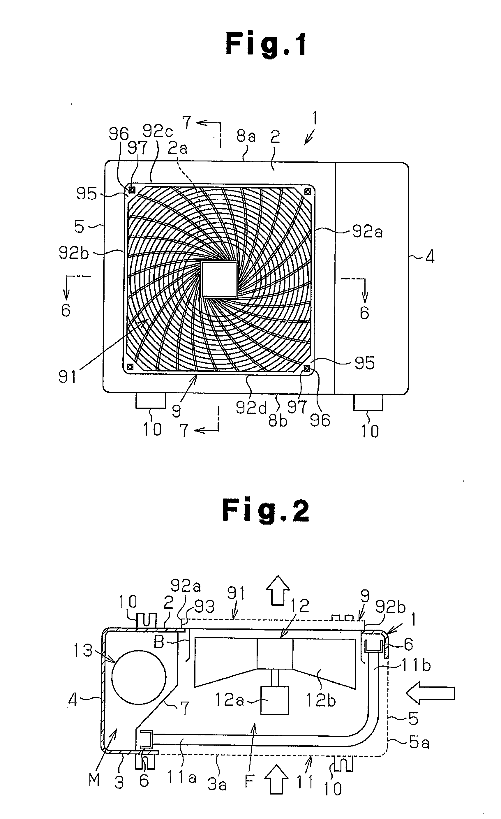
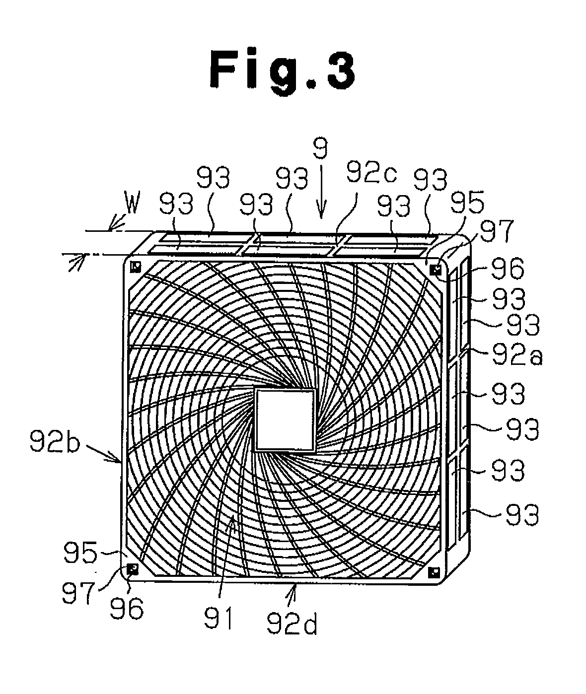
[0041]FIGS. 1 to 7 show the structure of an air delivery unit according to a first embodiment of the present invention as a whole and a main portion of the air delivery unit. In the present embodiment, the air delivery unit is embodied as an outdoor unit of an air conditioner.

[0042]As shown in FIGS. 1 and 2, the outdoor unit includes a heat exchanger 11, an air delivery device 12, and a casing 1. The casing 1 has a front plate 2, a rear plate 3, a pair of side plates 4, 5, a top plate 8a, and a bottom plate 8b. The heat exchanger 11 has an L shape as viewed from above. The heat exchanger 11 has an elongated portion 11a corresponding to the backside of the casing 1 and a short portion 11b corresponding to a side surface of the casing 1. The air delivery device 12 includes a fan motor 12a and a fan (a impeller) 12b. The casing 1 has a laterally elongated trunk-like shape. A compressor 13, which compresses refrigerant, is received in the casing 1. The fan motor 12a of the air delivery ...

second embodiment

[0057]FIGS. 11 and 12 show the structure of an air delivery unit according to a second embodiment of the present invention as a whole and a main portion of the air delivery unit. In the present embodiment, the air delivery unit is embodied as an outdoor unit of an air conditioner of a type that draws air from sides through three surfaces and blows the air upward.

[0058]The outdoor unit has a frame-like casing 1 with a rectangular cross section extending in the vertical direction. An air inlet 23a having a grill structure is formed in the entire portion of a front surface 23 of the casing 1. Air inlets 24a, 25a are each formed in the front surface of the corresponding one of two side surfaces 24, 25. A backside 22 of the casing 1 as a whole and rear portions of the side surfaces 24, 25 are formed by blind patches. A heat exchanger, which has a U shape as viewed from above, is received in the casing 1 in correspondence with the air inlet 23a of the front surface 23 and the air inlets 2...


PUM


Abstract

An air delivery unit includes a casing, an air delivery device arranged in a fan passage in the casing, and a fan guard that is arranged at an air outlet of the casing and has an air blowing surface having a grill structure and a hollow frame wall portion. An air blowing opening is formed in the frame wall portion of the fan guard. This structure allows the air to be blown also from the opening of the frame wall portion of the fan guard. This reduces the amount and the speed of the air blown from the air blowing surface of the fan guard having the grill structure. As a result, rise of static pressure of the air delivery device is suppressed and noise caused by interference between bars of an air blowing grill and the air is reduced.

Description

TECHNICAL FIELD[0001]The present invention relates to the structure of a fan guard arranged in an air delivery unit of an outdoor unit of an air conditioner or the like.BACKGROUND ART[0002]Typically, an air delivery unit, such as an outdoor unit of an air conditioner, has a fan guard having a grill structure, which covers an air outlet in order to ensure safety and protect blades of an air delivery device (see, for example, Patent Documents 1 to 3). However, the fan guard resists the stream of the air blown from the air outlet. In other words, the fan guard is one of the factors that raises the static pressure of the air delivery device. Also, interference between the air blown by the blades and the grill bars of the fan guard produces loud noise, which raises the level of the noise generated by the outdoor unit.[0003]This problem is substantially negligible in, for example, a fan guard 9 having a grill structure formed only by steel wires a, b, c, d, which fan guard 9 employs a gri...

Claims


Application Information

Patent Timeline
Patent Type & Authority Applications(United States)
IPC IPC(8): F24H3/02
CPCF24F1/38F24F1/40F24F1/54F24F1/48F24F1/50F24F1/46
Inventor NAKAGAWA, SUGURUYAMAMOTO, JIROUSHIGEMORI, MASAHIRO
Owner DAIKIN IND LTD
Why Eureka
Try Eureka