Extended reach battery charging system

a charging system and battery technology, applied in lighting support devices, lighting and heating apparatuses with built-in power, etc., can solve the problems of relatively long run-time and short charge time of batteries, and achieve the effects of short charge time, low power consumption, and long run-tim

a charging system and battery technology, applied in lighting support devices, lighting and heating apparatuses with built-in power, etc., can solve the problems of relatively long run-time and short charge time of batteries, and achieve the effects of short charge time, low power consumption, and long run-tim

US20110001455A1Active Publication Date: 2011-01-06VERSALITE ASSOCS

Image

  • Extended reach battery charging system
  • Extended reach battery charging system
  • Extended reach battery charging system

Examples


Embodiment Construction

Reference will now be made in detail to the embodiments of the invention which are illustrated in the accompanying drawings. The drawings are not necessarily to scale and certain components may be shown in schematic form in the interest of clarity and conciseness.

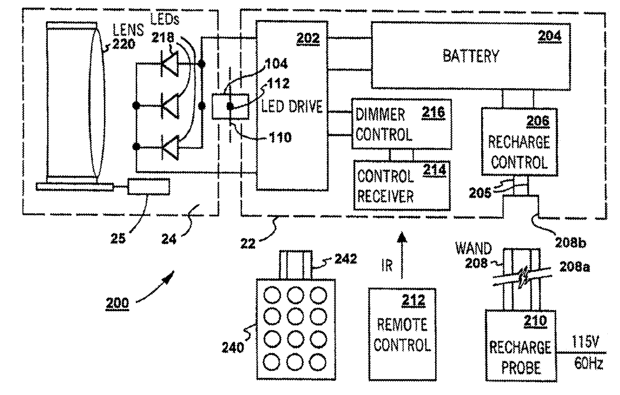
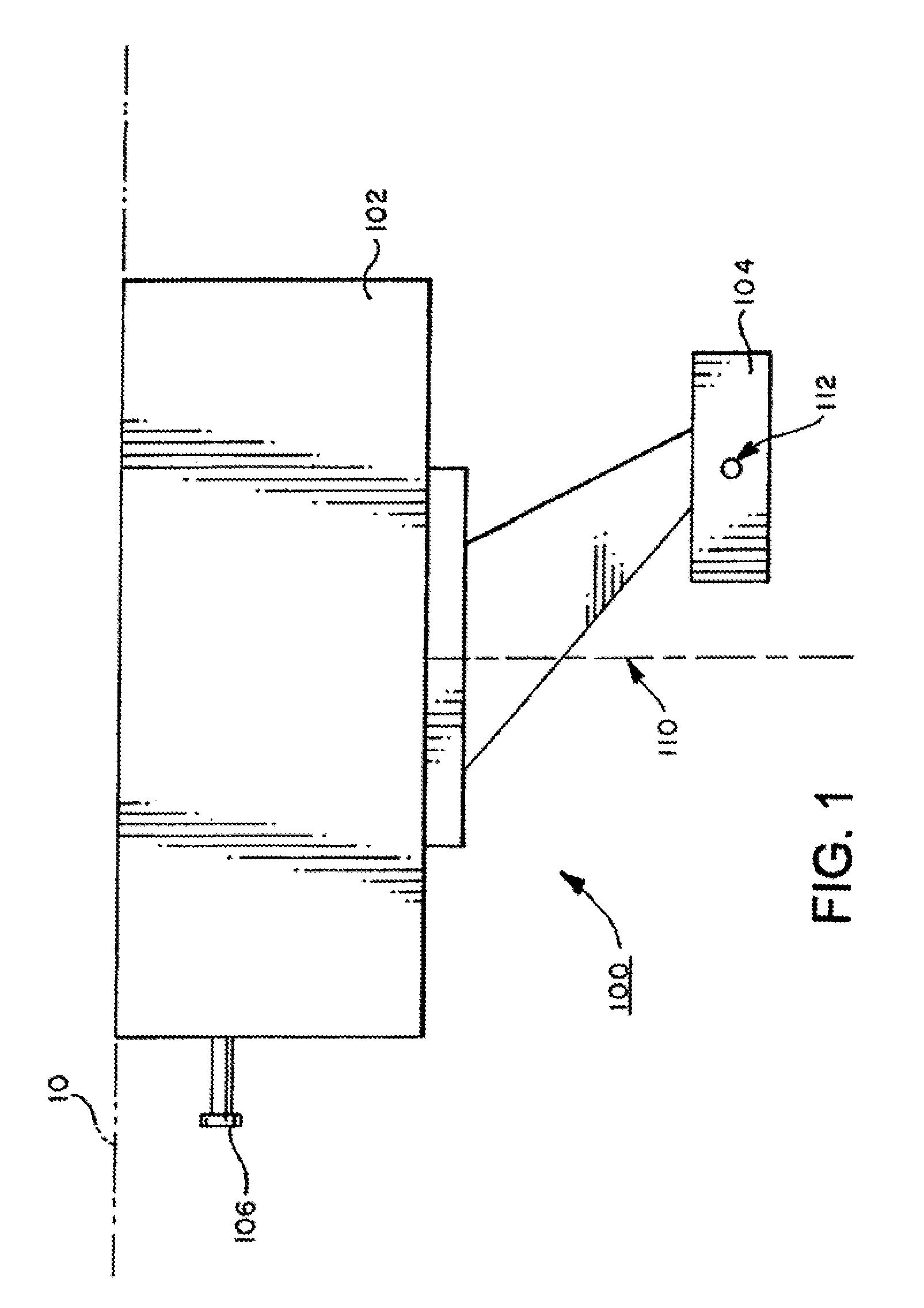
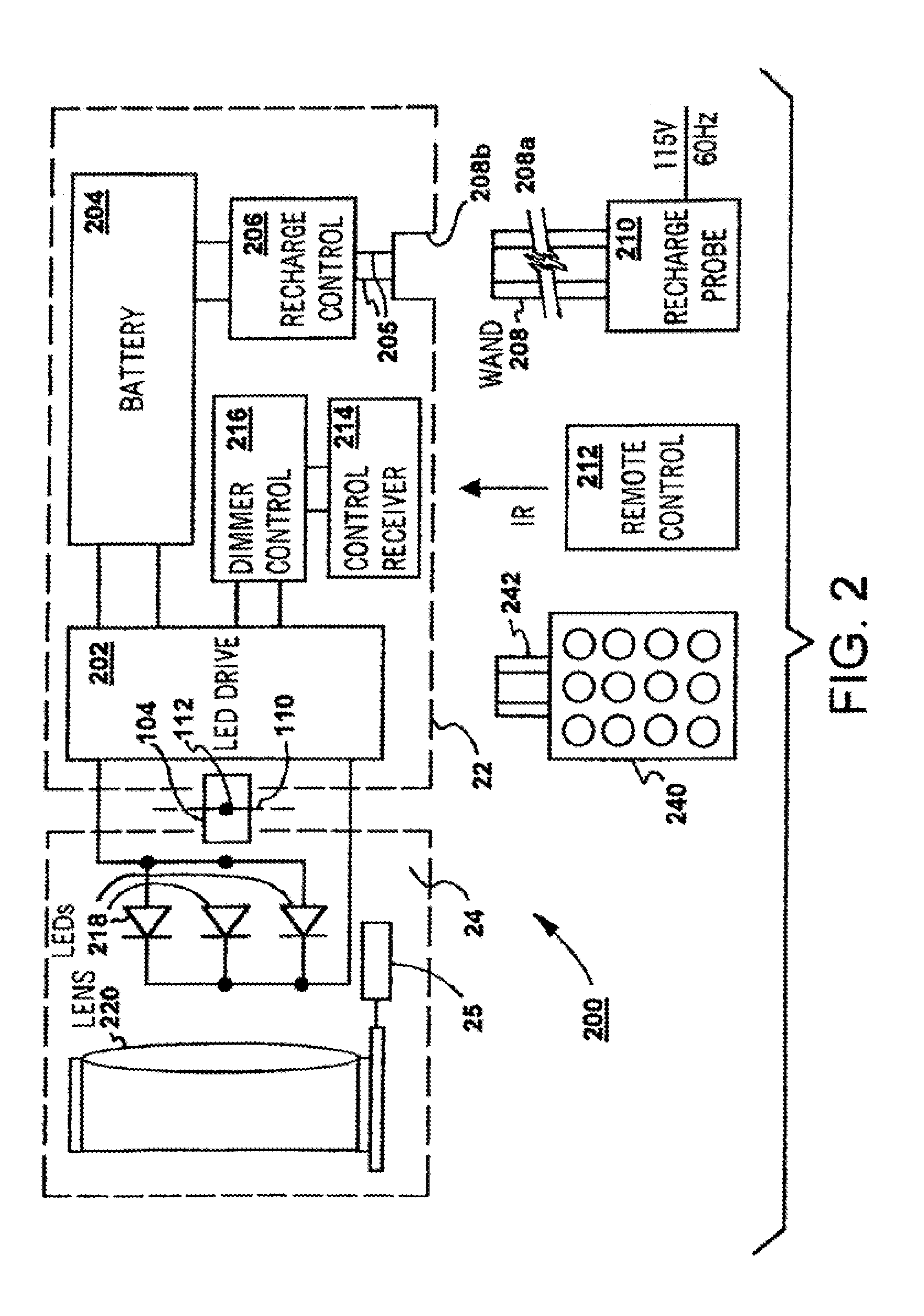
Referring to FIG. 1, there is shown an exemplary lighting device 100 according to one embodiment of the invention. The lighting device 100 may comprise two main components: a base 102 and a pan-tilt assembly 104. The base 102 may house electronics and one or more batteries. The pan-tilt assembly 104 may house a lens, one or more LEDs, and a heat sink.

The base 102 may be mounted to a surface 10 or a recess opening therein. The base 102 may be mounted via a number of mechanisms. For example, the base 102 may be screw-mounted via a ceiling mount or a wall mount, or the base 102 may include a hook and loop patch-type fastening means, an adhesive pad or other detachable mounting devices. Since the lighting device 100 is battery-...


PUM


Abstract

A charging system for use in charging a battery includes an elongate handle with a working length sufficient to reach a battery that is out of reach of a user. The charging system includes a charging apparatus coupled to the elongate handle. A head member is configured to mechanically engage with and electrically connect to a battery unit and also mechanically disengage and electrically disconnect from the battery unit by manually grasping and applying mechanical force to the elongate handle. The charging system also includes a power supply configured to provide electrical power to the charging apparatus. The charging system can be used to recharge the battery of a wall or ceiling mounted device (e.g., a battery powered lighting device) that is out of reach of the user without having to remove the device or use a ladder to reach the device.

Description

BACKGROUNDThe present invention relates to lighting devices, particularly to a versatile lighting device, and more particularly to a versatile lighting device for art gallery, display and decorative lighting applications.Picture lights and display lights have been widely used in public establishments (e.g., galleries and museums) to illuminate paintings, artifacts and architectural details for enhanced visual effects. Recently, these lighting devices are slowly making their way into private homes. Many people attempt to make their homes appear warmer and more attractive by installing what used to be considered professional lighting fixtures. Private individuals may also have the need to showcase a wide range of possessions, such as paintings, prints, photographs, awards, artifacts, plants, flowers, and aquariums. A variety of decorative lighting devices have been designed and marketed for these purposes. The known types of decorative lighting devices have at least the following draw...

Claims


Application Information

Patent Timeline
06 Jan 2011
Publication
US20110001455A1
IPC
H02J7/00
CPC
F21S9/02; F21V14/06; F21V23/0435; F21V23/04; H02J7/0042; F21S9/037; F21V21/15; F21Y2101/02
Inventors
DOWDY, RANDAL A.; GUYER, JEFFREY A.