Sub-diffraction limit image resolution in three dimensions

a three-dimensional, sub-diffraction limit technology, applied in the direction of instruments, optical elements, fluorescence/phosphorescence, etc., can solve the problems of electron microscopy using electrons, unsatisfactory limitations, and standard fluorescence microscopy not being useful for ultra-structural imaging,

Active Publication Date: 2011-01-06
PRESIDENT & FELLOWS OF HARVARD COLLEGE
View PDF31 Cites 81 Cited by
  • Summary
  • Abstract
  • Description
  • Claims
  • Application Information

AI Technical Summary

Benefits of technology

[0005]The present invention generally relates to sub-diffraction limit image resolution and other imaging techniques, including imaging in three dimensions. The subject matter of the present invention involves, in some cases, interrelated products, alternative solutions to a particular problem, and / or a plurality of different uses of one or more systems and / or articles.
[0006]In one aspect, the invention is directed to a method. In one set of embodiments, the method includes acts of providing a first entity and a second entity separated by a distance of less than about 1000 nm, determining light emitted by the first entity, determining light emitted by the second entity, and determining x, y, and z positions of the first entity and the second entity using the light emitted by the first entity and the light emitted by the second entity. The method, in another set of embodiments, includes acts of providing a first entity and a second entity separated by a distance of separation, determining light emitted by the first entity, determining light emitted by the second entity, and determining x, y, and z positions of the first entity and the second entity using the light emitted by the first entity and the light emitted by the second entity.
[0007]According to yet another set of embodiments, the method includes acts of providing a first entity and a second entity separated by a distance of less than about 1000 nm, activating the first entity but not the second entity, determining light emitted by the first entity, activating the second entity, determining light emitted by the second entity, and determining x, y, and z positions of the first entity and the second entity using the light emitted by the first entity and the light emitted by the second entity. In still another set of embodiments, the method includes acts of providing a first entity and a second entity separated by a distance of separation, activating the first entity but not the second entity, determining light emitted by the first entity, activating the second entity, determining light emitted by the second entity, and determining x, y, and z positions of the first entity and the second entity using the light emitted by the first entity and the light emitted by the second entity.
[0008]In one set of embodiments, the method includes acts of providing a plurality of entities able to emit light (at least some of which are separated by a distance of less than about 1000 nm), activating a fraction of the plurality of entities to emit light, determining the emitted light, deactivating the activated fraction of the plurality of entities, and repeating the acts of activating and deactivating the plurality of entities to determine x, y, and z positions of the plurality of entities. The method, in yet another set of embodiments, includes acts of providing a plurality of entities able to emit light, activating a fraction of the plurality of entities to emit light, determining the emitted light, deactivating the activated fraction of the plurality of entities, and repeating the acts of activating and deactivating the plurality of entities to determine x, y, and z positions of the plurality of entities.
[0009]In another aspect, the present invention is directed to a method of making one or more of the embodiments described herein. In another aspect, the present invention is directed to a method of using one or more of the embodiments described herein.
[0010]Other advantages and novel features of the present invention will become apparent from the following detailed description of various non-limiting embodiments of the invention when considered in conjunction with the accompanying figures. In cases where the present specification and a document incorporated by reference include conflicting and / or inconsistent disclosure, the present specification shall control. If two or more documents incorporated by reference include conflicting and / or inconsistent disclosure with respect to each other, then the document having the later effective date shall control.

Problems solved by technology

Despite these advantages, standard fluorescence microscopy is not useful for ultra-structural imaging, due to a resolution limit set by the diffraction of light.
Several approaches have been employed to try to pass this diffraction limit, including near-field scanning optical microscopy (NSOM), stimulated emission depletion (STED), reversible saturable optical linear fluorescence transition (RESOLFT), and saturated structured-illumination microscopy (SSIM), but each has certain unsatisfactory limitations.
Electron microscopy is often used for high resolution imaging of biological samples, but electron microscopy uses electrons, rather than light, and is difficult to use with biological samples due to its preparation requirements.

Method used


Image

  • Sub-diffraction limit image resolution in three dimensions
  • Sub-diffraction limit image resolution in three dimensions
  • Sub-diffraction limit image resolution in three dimensions

Examples


example 1

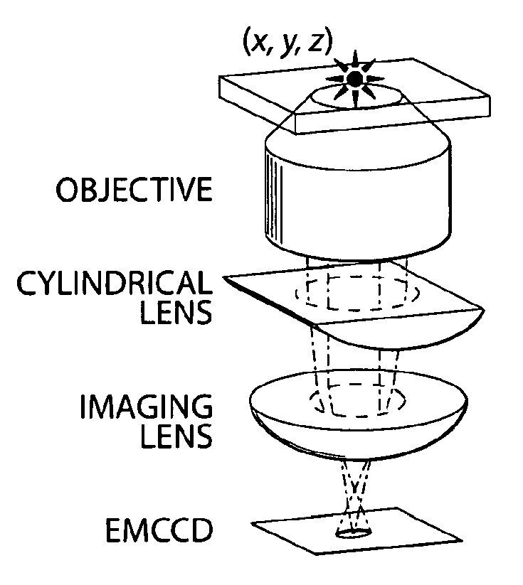
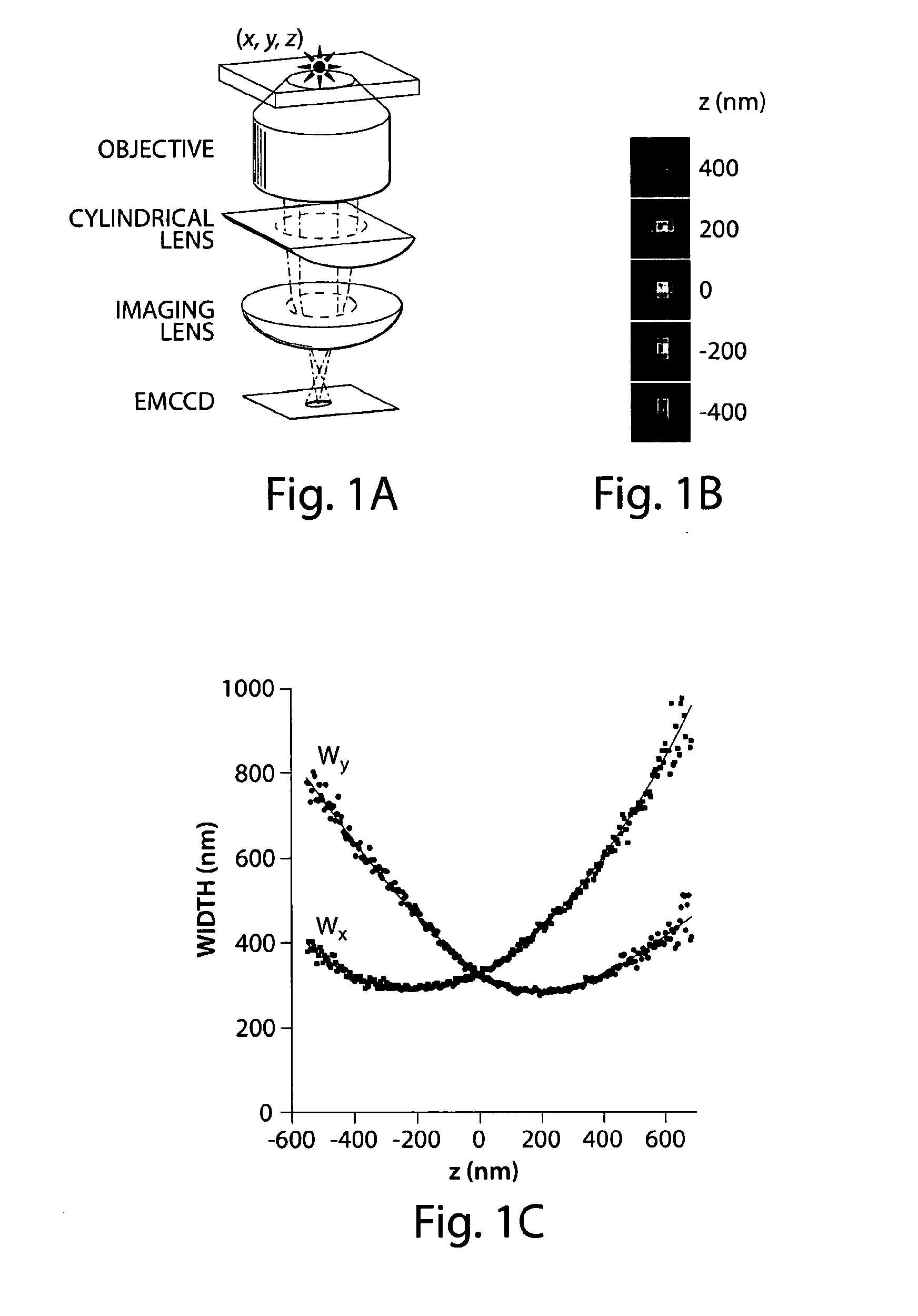
[0051]This example demonstrates 3-dimensional imaging with a spatial resolution that is about 10 times better than the diffraction limit in all three dimensions without invoking sample or optical beam scanning. In International Patent Application No. PCT / US2007 / 017618, filed Aug. 7, 2007, entitled “Sub-Diffraction Limit Image Resolution and Other Imaging Techniques,” published as Int. Pat. Apl. Pub. No. WO 2008 / 091296 on Jul. 31, 2008, incorporated herein by reference, the photoswitchable nature of certain fluorophores was used to separate the otherwise spatially overlapping images of numerous molecules, and high degrees of localization were achieved in the lateral dimensions for individual fluorescent dyes.

[0052]However, this example, and the following examples, illustrates imaging in all three dimensions by stochastic activation of an optically resolvable subset of photo switchable probes, determination of the coordinates for each probe with high accuracy, and construction of a th...

example 2

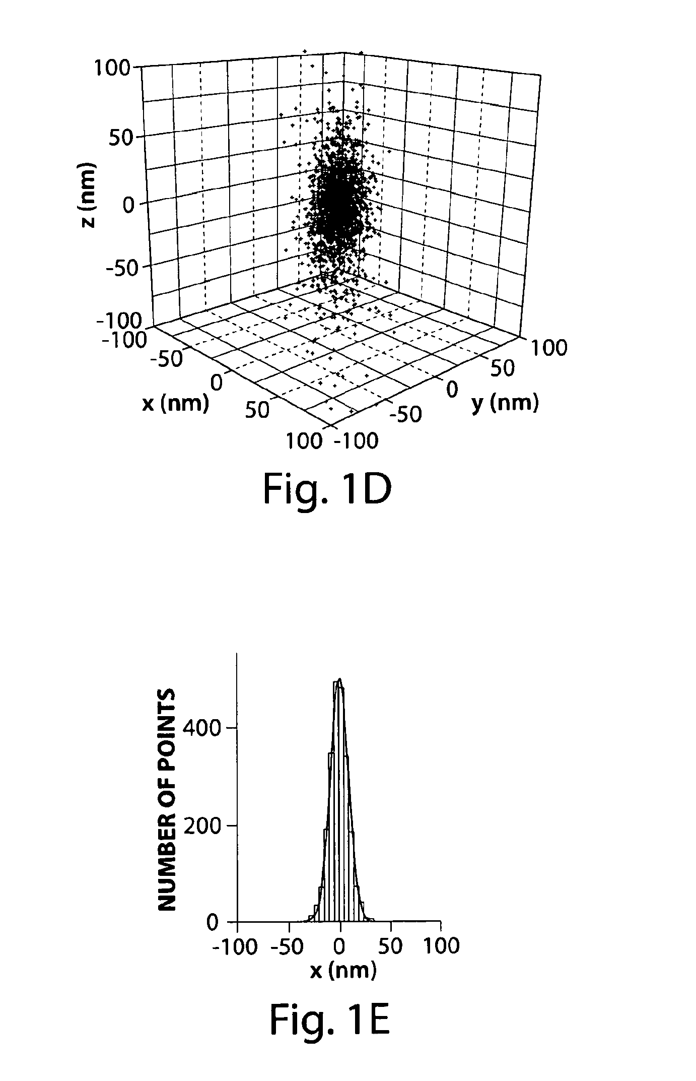
[0068]This example describes certain techniques useful with respect to Example 1. To characterize the 3D localization accuracy of the photoswitchable probes of Example 1, streptavidin molecules (Invitrogen) were labeled with photoswitchable Alexa 647 fluorophore (Invitrogen) and the activator dye Cy3 (GE Healthcare) by incubating the protein with amine-reactive dyes following the suggested protocol from the manufacturers. Unreacted dye molecules were removed by gel filtration using a Nap-5 column (GE Healthcare). The labeling ratio was characterized by a UV-Vis spectrophotometer, and the absorption spectrum indicated a labeling ratio of ˜2 Cy3 and ˜0.1 Alexa 647 per streptavidin molecule. The labeled streptavidin was then immobilized onto the surface of a glass flow chamber assembled from a glass slide and a #1.5 coverglass. Slides and coverglasses were cleaned by sonicating in 1 M potassium hydroxide for 15 min, followed by extensive washing with MilliQ water and drying with compre...


PUM


Abstract

The present invention generally relates to sub-diffraction limit image resolution and other imaging techniques, including imaging in three dimensions. In one aspect, the invention is directed to determining and/or imaging light from two or more entities separated by a distance less than the diffraction limit of the incident light. For example, the entities may be separated by a distance of less than about 1000 nm, or less than about 300 nm for visible light. In some cases, the position of the entities can be determined in all three spatial dimensions (i.e., in the x, y, and z directions), and in certain cases, the positions in all three dimensions can be determined to an accuracy of less than about 1000 nm. In one set of embodiments, the entities may be selectively activatable, i.e., one entity can be activated to produce light, without activating other entities. A first entity may be activated and determined (e.g., by determining light emitted by the entity), then a second entity may be activated and determined. The emitted light may be used to determine the x and y positions of the first and second entities, for example, by determining the positions of the images of these entities, and in some cases, with sub-diffraction limit resolution. In some cases, the z positions may be determined using one of a variety of techniques that uses intensity information or focal information (e.g., a lack of focus) to determine the z position. Non-limiting examples of such techniques include astigmatism imaging, off-focus imaging, or multi-focal-plane imaging.

Description

RELATED APPLICATIONS[0001]This application claims the benefit of U.S. Provisional Patent Application Ser. No. 61 / 008,661, filed Dec. 21, 2007, entitled “Sub-Diffraction Limit Image Resolution in Three Dimensions,” by Zhuang, et al., incorporated herein by reference.GOVERNMENT FUNDING[0002]Research leading to various aspects of the present invention were sponsored, at least in part, by the National Institutes of Health. The U.S. Government has certain rights in the invention.FIELD OF INVENTION[0003]The present invention generally relates to sub-diffraction limit image resolution and other imaging techniques, including imaging in three dimensions.BACKGROUND[0004]Fluorescence microscopy is widely used in molecular and cell biology and other applications for non-invasive, time-resolved imaging. Despite these advantages, standard fluorescence microscopy is not useful for ultra-structural imaging, due to a resolution limit set by the diffraction of light. Several approaches have been empl...

Claims


Application Information

Patent Timeline
Patent Type & Authority Applications(United States)
IPC IPC(8): G06K9/00
CPCG01N21/6428G01N21/6458G01N2021/6419G01N2021/6421G01N2021/6441H04N13/0203G02B21/361G02B21/367G02B27/58G01N21/64H04N7/18G02B21/16H04N13/204G01N2021/6439
Inventor ZHUANG, XIAOWEIHUANG, BOBATES, WILFRED M.WANG, WENQIN
Owner PRESIDENT & FELLOWS OF HARVARD COLLEGE
Why Eureka
Try Eureka