Shielded three-terminal flat-through emi/energy dissipating filter

a flat-through emi/energy dissipation filter and shielding technology, which is applied in the direction of feed-through capacitors, coupling device connections, therapy, etc., can solve the problems of high cost, high attenuation, and complex design, and achieves high through circuit current, high through-circuit current, and the effect of maximizing the value of flat-through capacitan

Inactive Publication Date: 2011-01-06
WILSON GREATBATCH LTD
View PDF99 Cites 39 Cited by
  • Summary
  • Abstract
  • Description
  • Claims
  • Application Information

AI Technical Summary

Benefits of technology

A primary objective of the present invention is to provide a novel shielded three-terminal flat-through EMI / energy dissipating filter which embodies one or more flat-through capacitors whose internal electrodes are high frequency shielded, are much thicker (compared to prior art MLCC flat-through thick film electrode technology) and higher in both cross-sectional and surface area (robust and able to carry much higher through circuit currents), whose electrodes can be configured with integral co-planar inductor elements, and can be optionally configured to accept a variety of surface mounted electronic components (like additional discrete or embedded capacitors, inductors, diodes, RFID chips, and the like). The higher surface area of the novel shielded three-terminal flat-through EMI / energy dissipating filter of the present invention maximizes the value of the flat-through capacitance. The present invention resides in a shielded three-terminal flat-through EMI / energy dissipating filter which comprises an active electrode plate through which a circuit current passes between a first terminal and a second terminal, and a plurality of shield plates substantially enveloping the active electrode plate, wherein the shield plates are conductively coupled to a grounded third terminal. Preferably, the plurality of shield plates include a first shield plate on a first side of the active electrode plate, and a second shield plate on a second side of the active electrode plate opposite the first shield plate. The active electrode plate is insulated from the shield plates by a dielectric material such that the active electrode plate and the shield plates cooperatively form a flat-through capacitor. A lead wire typically extends through at least one of the shield plates in non-conductive relation. The lead wire is conductively coupled to the active electrode plate to form the first terminal. A shielded fixture may be provided through which the lead wire extends in non-conductive relation. The fixture may comprise an hermetic seal for, for example, an active implantable medical device (AIMD). The surface area of the active electrode plate is maximized to increase parasitic capacitance and minimize resistance to current flow.
It will be appreciated that the basic point of novelty of the three-terminal flat-through EMI / energy dissipating filter is that it comprises an active electrode plate through which a circuit current passes between a first terminal and a second terminal, a first shield plate on a first side of the active electrode plate, and second shield plate on a second side of the active electrode plate opposite the first shield plate, wherein the first and second shield plates are conductively coupled to a grounded third terminal. The effective capacitance area or overlapping surface area of the active electrode plate and its surrounding grounded shield plates have been relatively maximized in order to achieve a higher value of capacitance of the three-terminal flat-through capacitor. The dielectric constant of the insulating layers between the active electrode plate and the surrounding ground shied plates have also been substantially raised in order to achieve a higher capacitance value for the three-terminal flat-through capacitor. Preferably, the dielectric thickness separating the active electrode plate and the surrounding ground shield plate is relatively minimized in order to achieve a higher capacitance value. A number of redundant parallel layers of the active electrode plate and surrounding grounded shield plates are provided to increase the total capacitance value of the three-terminal flat-through capacitor.

Problems solved by technology

These devices tend to be more sensitive to EMI than passive pumps that have no sense circuitry or externally implanted lead wires.
Cell phones, microwave ovens and the like have all been implicated in causing interference with active implantable medical devices.
However, as the MLCC nears its self-resonant frequency (SRF), its attenuation tends to go up dramatically.
This is an undesirable effect and this is why feedthrough capacitors have generally been the preferred choice for use in EMI broadband filters.
Referring once again to FIG. 19, the reason why this approach has never been commonly practiced in the AIMD market is the fact that this is a complicated design and is also costly.
Because of the space limitations and reliability implications, packing this many components into such a small place becomes impractical.
In the industry, this is known as the tombstone mounting position, which is a highly undesirable thing to do when the capacitor is to be used as an EMI filter or an RF decoupling device (bad mounting and bad form factor).
The reason this is undesirable is this particular capacitor will tend to self-resonate at a much lower frequency (and thereby becomes a less effective high frequency device or EMI filter).
At very high frequencies, such as above 1 GHz, this problem becomes quite serious.
Monolithic ceramic manufacturing limitations on electrode thickness and conductivity means that prior art flat-through capacitors 174 have relatively high series resistance and can only be rated to a few hundred milliamps or a few amps at best (however, an implantable defibrillator must deliver a high voltage pulse of over 20-amps).
However, because of this cross-coupling, there is always going to be a certain frequency at which the attenuation starts to parasitically drop off as shown.
This drop off is very undesirable in active implantable medical device (AIMD) applications in that there would be less protection against high frequency EMI emitters such as cellular phones and the like.
This parasitic drop off in attenuation due to cross-coupling is even a worse problem in military and space applications where EMI filter attenuation requirements of up to 10 or even 18 GHz, is important (implantable medical applications don't generally require filtering much above 3 GHz due to the effective reflection and absorption of human skin of RF energy at frequencies above 3 GHz).

Method used


Image

  • Shielded three-terminal flat-through emi/energy dissipating filter
  • Shielded three-terminal flat-through emi/energy dissipating filter
  • Shielded three-terminal flat-through emi/energy dissipating filter

Examples


Embodiment Construction

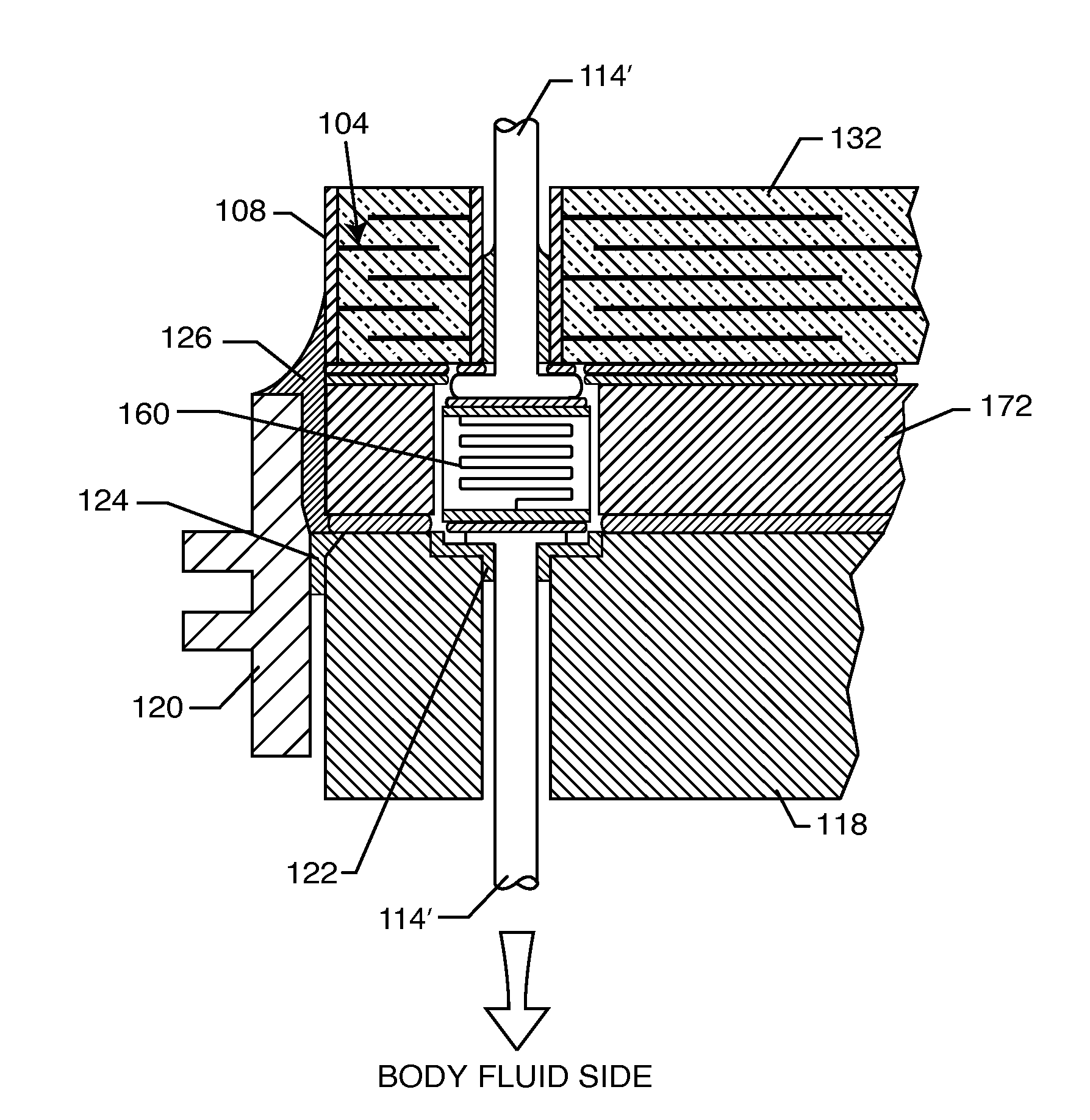
As shown in the drawings for purposes of illustration, the present invention is concerned with shielded three-terminal flat-through EMI / energy dissipating filters 190 which can be embodied in substrates or flex cable assemblies. The novel concept resides in designing an embedded flat-through capacitor wherein optional surface mounted passive or active components can be attached while at the same time providing an interconnection circuit. The novel shielded three-terminal flat-through EMI / energy dissipating filters 190 embody a flat-through capacitor that has similar characteristics to prior art feedthrough EMI filter capacitors. The flat-through EMI / energy dissipating filter 190 of the present invention provides three-terminal capacitive filtering while simultaneously providing shielding of circuits and signals passing through the robust high current capability electrodes of the flat-through capacitor. The flat-through EMI / energy dissipating filter 190 of the present invention funct...


PUM


Abstract

A shielded three-terminal flat-through EMI / energy dissipating filter includes an active electrode plate through which a circuit current passes between a first terminal and a second terminal, a first shield plate on a first side of the active electrode plate, and a second shield plate on a second side of the active electrode plate opposite the first shield plate. The first and second shield plates are conductively coupled to a grounded third terminal. In preferred embodiments, the active electrode plate and the shield plates are at least partially disposed with a hybrid flat-through substrate that may include a flex cable section, a rigid cable section, or both.

Description

BACKGROUND OF THE INVENTIONThe present invention relates generally to feedthrough filter capacitor EMI filters. More particularly, the present invention relates to a hybrid EMI filter substrate and / or flex cable assembly which embodies embedded shielded flat-through / feedthrough filters and / or energy dissipating circuit elements. This invention is applicable to a wide range of connectors, terminals and / or hermetic seals that support lead wires as they ingress / egress into electronic modules or shielded housings. In particular, the present invention applies to a wide variety of active implantable medical devices (AIMDs).FIGS. 1-40 provide a background for better understanding the significance and novelty of the present invention.FIG. 1 illustrates various types of active implantable and external medical devices 100 that are currently in use. FIG. 1 is a wire formed diagram of a generic human body showing a number of implanted medical devices. 100A represents a family of hearing devices...

Claims


Application Information

Patent Timeline
Patent Type & Authority Applications(United States)
IPC IPC(8): A61N1/00
CPCA61N1/3754H01G4/40H01R13/7195H03H1/0007H01G4/35H05K9/00H05K5/0095H03H2001/0085H03H7/1766A61N1/08A61N1/375A61N1/3718A61N2001/086H03H2001/0042A61N1/086H05K1/181H05K2201/10015H01G4/06H05K999/99
Inventor STEVENSON, ROBERT A.TRUEX, BUEHL E.BRENDEL, RICHARD L.FRYSZ, CHRISTINE A.DABNEY, WARREN S.HUSSEIN, HAYTHEMLORENTE-ADAME, JOSE LUISJOHNSON, ROBERT SHAWNBRAINARD, SCOTTWILLIAMS, CHRISTOPHER MICHAEL
Owner WILSON GREATBATCH LTD
Why Eureka
Try Eureka