Vehicular air-conditioning system

a technology of air-conditioning system and window glass, which is applied in the direction of ventilation system, vehicle cleaning, heating types, etc., can solve the problems of drop in the heat exchange efficiency of the outside heat exchanger, and achieve the effect of improving the defogging ability of the window glass and improving practicality

Inactive Publication Date: 2011-01-13
DENSO CORP
View PDF6 Cites 72 Cited by
  • Summary
  • Abstract
  • Description
  • Claims
  • Application Information

AI Technical Summary

Benefits of technology

[0046]According to this, when the vent mode switch (60c) is used to set the defogging mode, the cooler cycle is selected and the window glass heating means (47) is operated, so it is possible to dry the vented air at the cooler cycle and possible to heat the vehicle window glass by the window

Problems solved by technology

In the past, in this type of vehicular air-conditioning system, there was the problem that when performing heating by the heat pump cycle at the time of a l

Method used


Image

  • Vehicular air-conditioning system
  • Vehicular air-conditioning system
  • Vehicular air-conditioning system

Examples


first embodiment

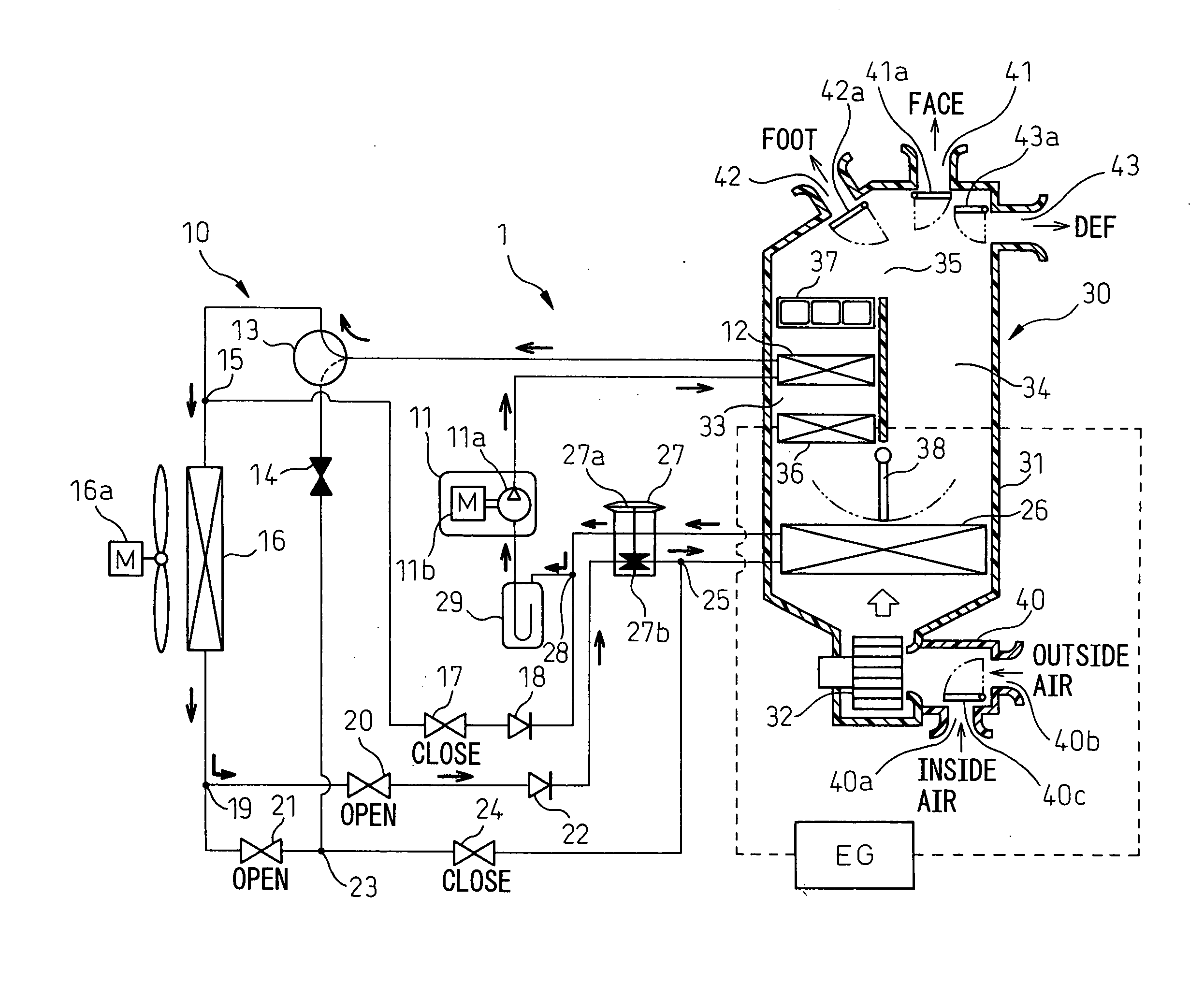
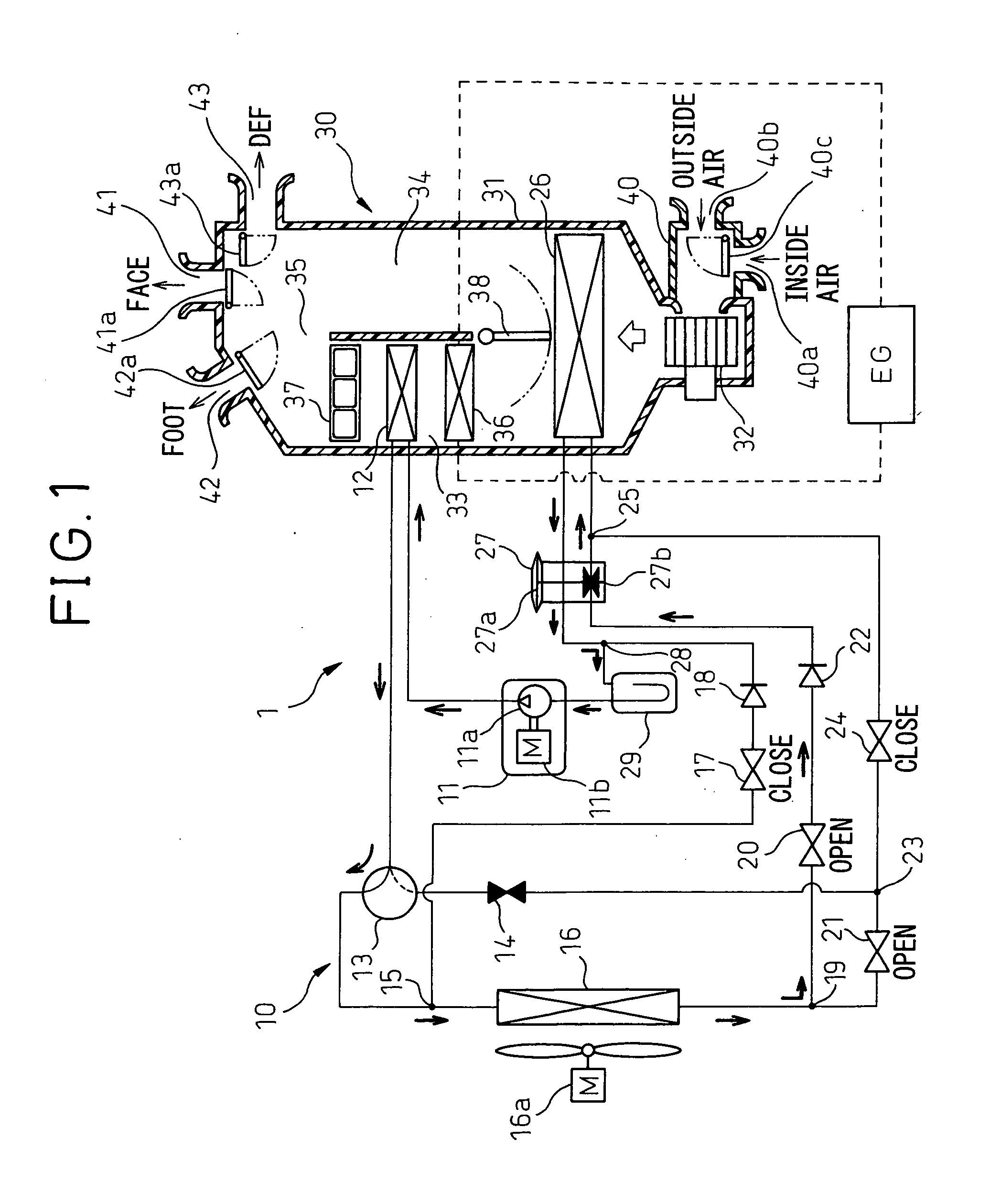
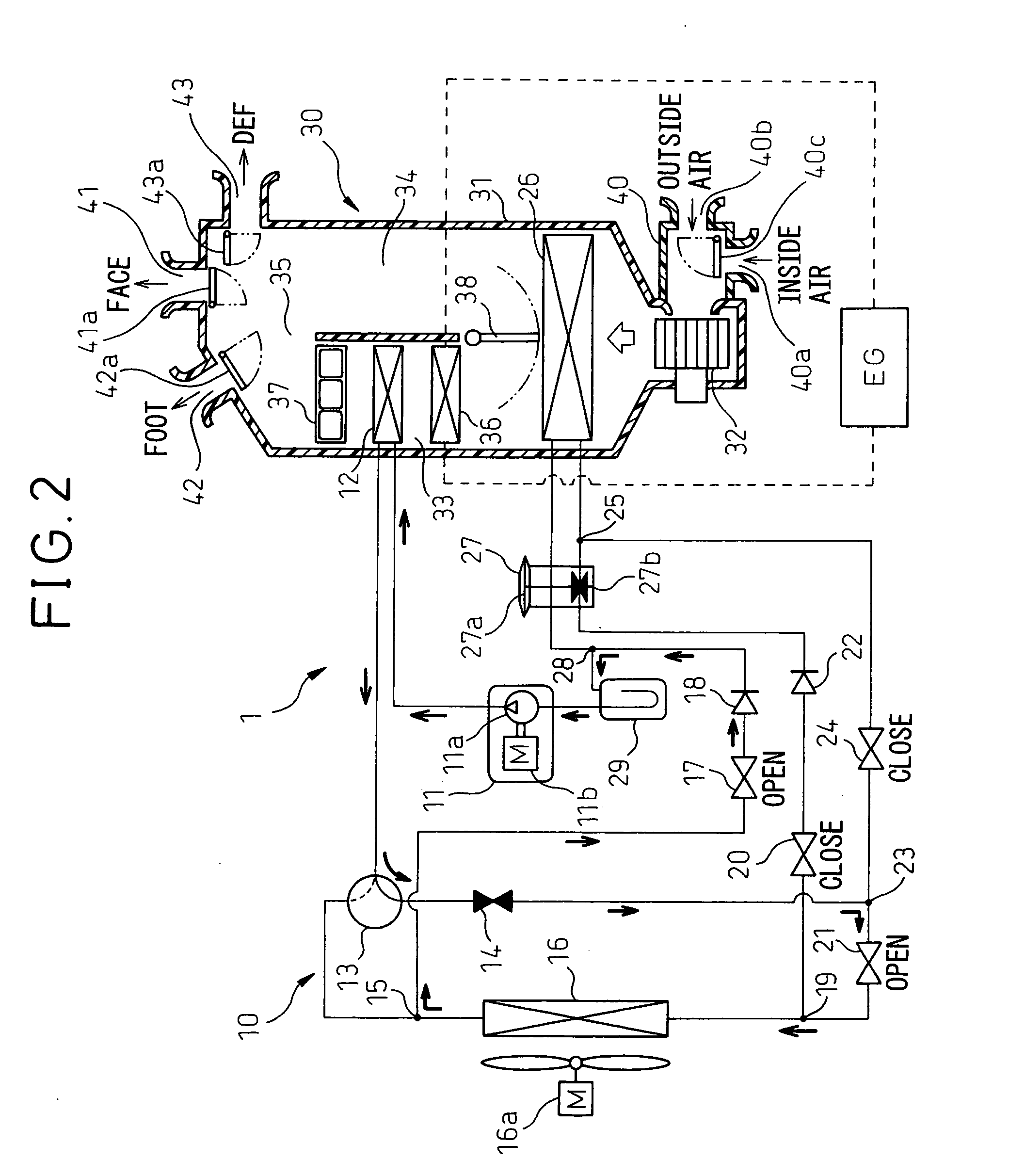
[0070]FIG. 1 to FIG. 9 will be used to explain a first embodiment of the present invention. In the present embodiment, the vehicular air-conditioning system of the present invention is applied to a so-called hybrid vehicle obtaining drive power for vehicle operation from an internal combustion engine (engine) EG and a drive use electric motor. FIG. 1 to FIG. 4 are overall views of the configuration of the vehicular air-conditioning system 1.

[0071]This vehicular air-conditioning system is provided with a vapor compression type refrigeration cycle 10 configured to be able to switch among refrigerant circuits of a cooling mode cooling an inside of a cabin (COOL cycle), a heating mode heating the inside of the cabin (HOT cycle), a first drying mode drying the inside of the cabin (DRY EVA cycle), and a second drying mode (DRY ALL cycle). FIG. 1 to FIG. 4 show the flows of refrigerant at the time of the cooling mode, heating mode, and first and second drying modes by solid line arrows.

[00...

second embodiment

[0230]FIG. 10 is a flowchart showing main parts of step S6 in the present second embodiment. The control processing of the flowchart of FIG. 10 is executed when the air-conditioner switch 60a and auto switch are on (ON) etc.

[0231]First, at step S60, it is judged if the time is that for pre-air-conditioning. When it is judged that the time is that for pre-air-conditioning (case of YES judgment), the routine proceeds to step S61 where it is judged if the outside air temperature is lower than a predetermined threshold value (in the example of FIG. 10, −3° C.)

[0232]When it is judged that the outside air temperature is lower than a predetermined threshold value (case of YES judgment), the routine proceeds to step S62 where it is decided to activate the PTC heaters 37. That is, at the time of pre-air-conditioning, the power switch of the hybrid system of the vehicle is off (OFF) in state, so the engine EG cannot be started up. For this reason, it is not possible to raise the cooling water...

third embodiment

[0251]In the above first embodiment, when the mode is the DEF and manual F / D and the cooler cycle is selected, the heat source required for heating is secured by the engine cooling water, but in the present third embodiment, as shown in FIG. 11, when the mode is the DEF and manual F / D and the cooler cycle is selected, the heat source required for heating is secured by the PTC heaters 37.

[0252]The flowchart of FIG. 11 changes the steps S33 and S34 of the flowchart of FIG. 9 to step S83, but otherwise is the same as the flowchart of FIG. 9.

[0253]When it is judged at step S82 (corresponding to step S32 of FIG. 9) that the window glass surface relative humidity RHW is higher than 90 (case of YES judgment), it is judged that there is the possibility of window fogging and the routine proceeds to step S83 where the number of PTC heaters 37 operated is increased to secure the heat sources required for heating.

[0254]In this embodiment, the number of PTC heaters 37 operated (number powered) i...


PUM


Abstract

A vehicular air-conditioning system provided with a vapor compression type refrigerating machine improved in practicality, provided with a vapor compression type refrigeration cycle 10 having a compressor 11 compressing and discharging a refrigerant and an outside heat exchanger 16 exchanging heat with the air outside of the cabin and the refrigerant and designed to be able to switch between a cooler cycle cooling vented air blown into the cabin and a heat pump cycle heating the vented air, a heating means 36 for using cooling water of an internal combustion engine EG as a heat source for heating the vented air, a vent mode switch 60c setting a defogging mode blowing out vented air toward the vehicle window glass by operation by a passenger, and a control means 50 controlling switching between the cooler cycle and heat pump cycle, the control means 50 selecting the cooler cycle and outputting a signal requesting operation to the internal combustion engine EG when the vent mode switch 60c is used to set the defogging mode.

Description

TECHNICAL FIELD[0001]The present invention relates to a vehicular air-conditioning system provided with a vapor compression type refrigerating machine forming a heat pump cycle.BACKGROUND ART[0002]In the past, in this type of vehicular air-conditioning system, there was the problem that when performing heating by the heat pump cycle at the time of a low outside air temperature, frost would form on an outside heat exchanger resulting in a drop in the heat exchange efficiency of the outside heat exchanger.[0003]Therefore, in the prior art of Patent Literature 1, when frost forms on the outside heat exchanger, the cooler cycle is switched to so as to run high temperature refrigerant through the outside heat exchanger and remove the frost from the outside heat exchanger.[0004]Further, in this prior art, even when frost forms on the outside heat exchanger, when the DEF mode (defroster mode) is selected for blowing warm air on the surface of the vehicle window glass on the cabin side, the...

Claims


Application Information

Patent Timeline
IPC IPC(8): F25B27/00B60S1/54B60H1/02F24F7/00B60H1/32
CPCB60H1/00785B60H2001/3266B60H1/321B60H1/00921
Inventor TANIHATA, TAKUYAEGAMI, HIROTAKAKURATA, SHUNICHISHI, YOSHINORI
Owner DENSO CORP
Why Eureka
Try Eureka