
High efficiency refrigerator

a refrigerator and high efficiency technology, applied in the field of refrigerators, can solve the problems of environmental waste, high energy consumption, and high cost of consumers, and achieve the effects of reducing the condensing pressure of the refrigeration system, reducing the cost of consumption, and increasing the capacity

Inactive Publication Date: 2011-01-20
WHIRLPOOL CORP
View PDF27 Cites 101 Cited by
  • Summary
  • Abstract
  • Description
  • Claims
  • Application Information

AI Technical Summary

Benefits of technology

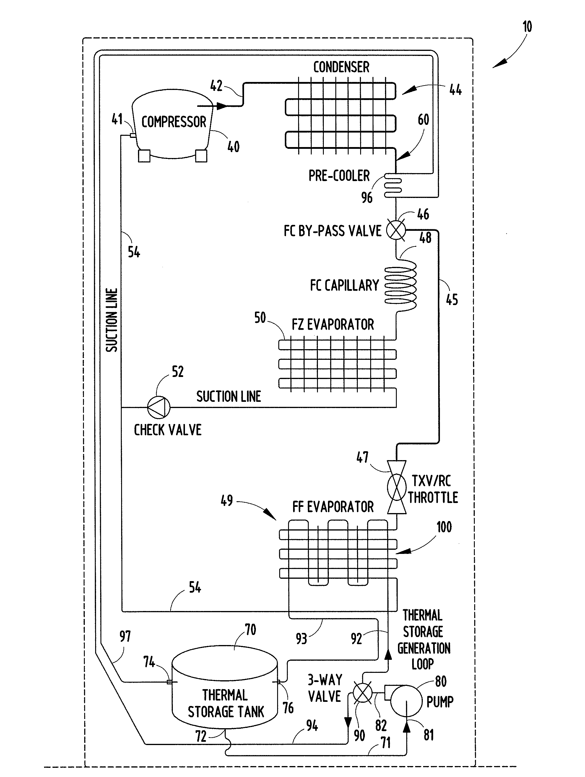
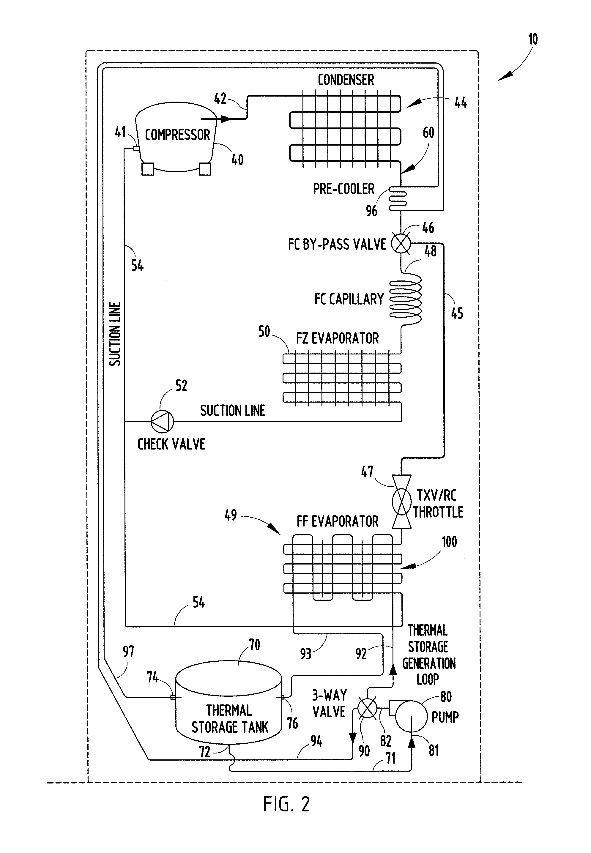
[0004]In order to draw upon the benefits of the variable and higher capacity available with a linear compressor, the thermal storage system of the present invention stores thermal energy (i.e., a coolant) in a thermal storage unit with the compressor operating at a higher capacity during low load conditions. Under high demand situations, the stored coolant can be circulated in a heat exchanger for cooling the fresh food refrigerator compartment or be coupled in a circulation circuit to sub-cool the output of the condenser, lowering the condensing pressure of the refrigeration system and, thus, increasing the cooling capacity output of the compressor and offsetting the need to size the compressor and condenser for highest estimated demand based solely on condenser heat transfer limitations within a given ambient air temperature condition. Also, the stored coolant can simultaneously flow through both circulation circuits. In either mode, the operating efficiency of the refrigerator is improved by taking advantage of the capacity of the linear compressor in providing coolant which can be stored when the full capacity of the compressor is not needed for normal refrigerator operation.
[0006]In a preferred embodiment of the invention, a three-way valve is coupled from the output pump to couple the stored coolant selectively to one or the other or both of the coolant circuits. In another preferred embodiment of the invention, the thermal storage unit comprises a thermal storage tank for water or a water / alcohol mix or other secondary coolant typically used in a refrigeration system. Although the system is most efficient when used with a linear compressor having sufficient capacity to cool the liquid coolant for storage in the insulated thermal storage tank, it can also be used with a conventional rotary compressor to even out the demand on the compressor.

Problems solved by technology

This results in the utilization of a significant amount of energy, which is environmentally wasteful and expensive for the consumer.

Method used


Image

  • High efficiency refrigerator
  • High efficiency refrigerator
  • High efficiency refrigerator

Examples


Embodiment Construction

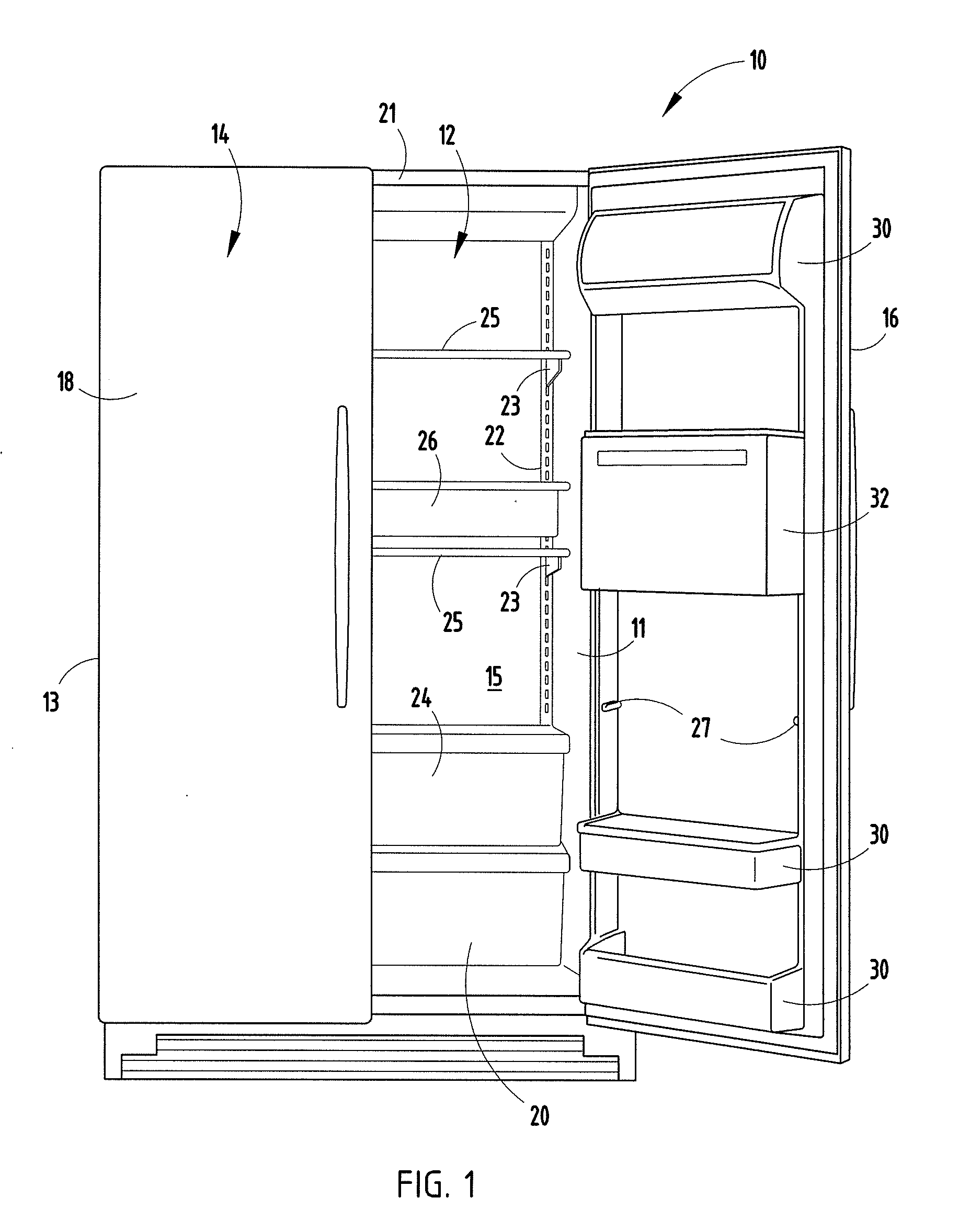
[0012]Referring initially to FIG. 1, there is shown a refrigerator freezer 10 embodying the present invention, which includes a side-by-side refrigerated cabinet 12 and a freezer cabinet 14. Each of the cabinets 12 and 14 include side walls 11 and 13, respectively, and a rear wall 15. Refrigerator 10 also includes a closure door 16 for the refrigerator cabinet 12 which is hinged to cabinet 12 and a freezer door 18 hinged to the freezer cabinet 14. Both doors 16 and 18 include suitable seals for providing an airtight thermally insulated sealed connection between the doors and respective cabinets. Although a side-by-side refrigerator / freezer is illustrated in FIG. 1, the present invention can be employed with any configuration of a refrigerator / freezer combination.

[0013]Refrigerator 10 is adapted to receive a variety of shelves and modules at different positions defined by, in the embodiment shown in FIG. 1, a plurality of horizontally spaced vertical rails 22 extending from the rear ...


PUM


Abstract

A thermal storage container is coupled to a pump for circulating cooled liquid from the thermal storage container in at least one of two circuits. One circuit includes a heat exchanger coupled to the fresh food evaporator for assisting in cooling the fresh food section of the refrigerator or for chilling the liquid. Another circuit includes a sub-cooler between the compressor and condenser for cooling the hot gas output from the compressor before entering the condenser, thereby increasing the efficiency of the system. A three-way valve is coupled from the output pump to couple the stored coolant selectively to one or the other or both of the coolant circuits.

Description

BACKGROUND OF THE INVENTION[0001]The present invention relates to a refrigerator including a freezer compartment and fresh food refrigeration compartment and particularly a thermal storage system for maximizing the efficiency of operation of the refrigerator.[0002]Refrigerators typically cycle on and off depending upon the frequency of use, the content, and the surrounding environmental conditions. With conventional refrigerators, the refrigerator compressor runs at maximum capacity regardless of load demands. This results in the utilization of a significant amount of energy, which is environmentally wasteful and expensive for the consumer. Linear compressors, such as disclosed in U.S. Patent Publication 2006 / 00110259, the disclosure of which is incorporated herein by reference, are capable of a variable operating capacity ranging in the neighborhood of a ratio of 5:1. Linear compressors, thus, can be controlled to meet the actual demand for refrigerators but also have the benefit o...

Claims


Application Information

Patent Timeline
IPC IPC(8): F25D17/02F25B1/00F25D11/02
CPCF25D11/025F25D13/04F25B40/02F25B2309/001F25B2400/24F25B2400/052F25B1/00F25D16/00F25B5/02F25B2600/2511F25D11/022F25D17/02
Inventor KUEHL, STEVEN J.WU, GUOLIAN
Owner WHIRLPOOL CORP
Learn More