Oxyfuel Boiler and Control Method for Oxyfuel Boiler

Inactive Publication Date: 2011-01-20
HITACHI LTD
View PDF56 Cites 30 Cited by
  • Summary
  • Abstract
  • Description
  • Claims
  • Application Information

AI Technical Summary

Benefits of technology

[0028]According to the present invention, when a coal boiler operated as an existing air-fuel boiler is operated as an oxyfuel boiler, the expense required for modification can be suppressed, and the damage to th

Problems solved by technology

Furthermore, in some of the heat exchangers, if the heat absorption rate is excessively larger than that under the air-fuel combustion c

Method used


Image

  • Oxyfuel Boiler and Control Method for Oxyfuel Boiler
  • Oxyfuel Boiler and Control Method for Oxyfuel Boiler
  • Oxyfuel Boiler and Control Method for Oxyfuel Boiler

Examples


embodiment 1

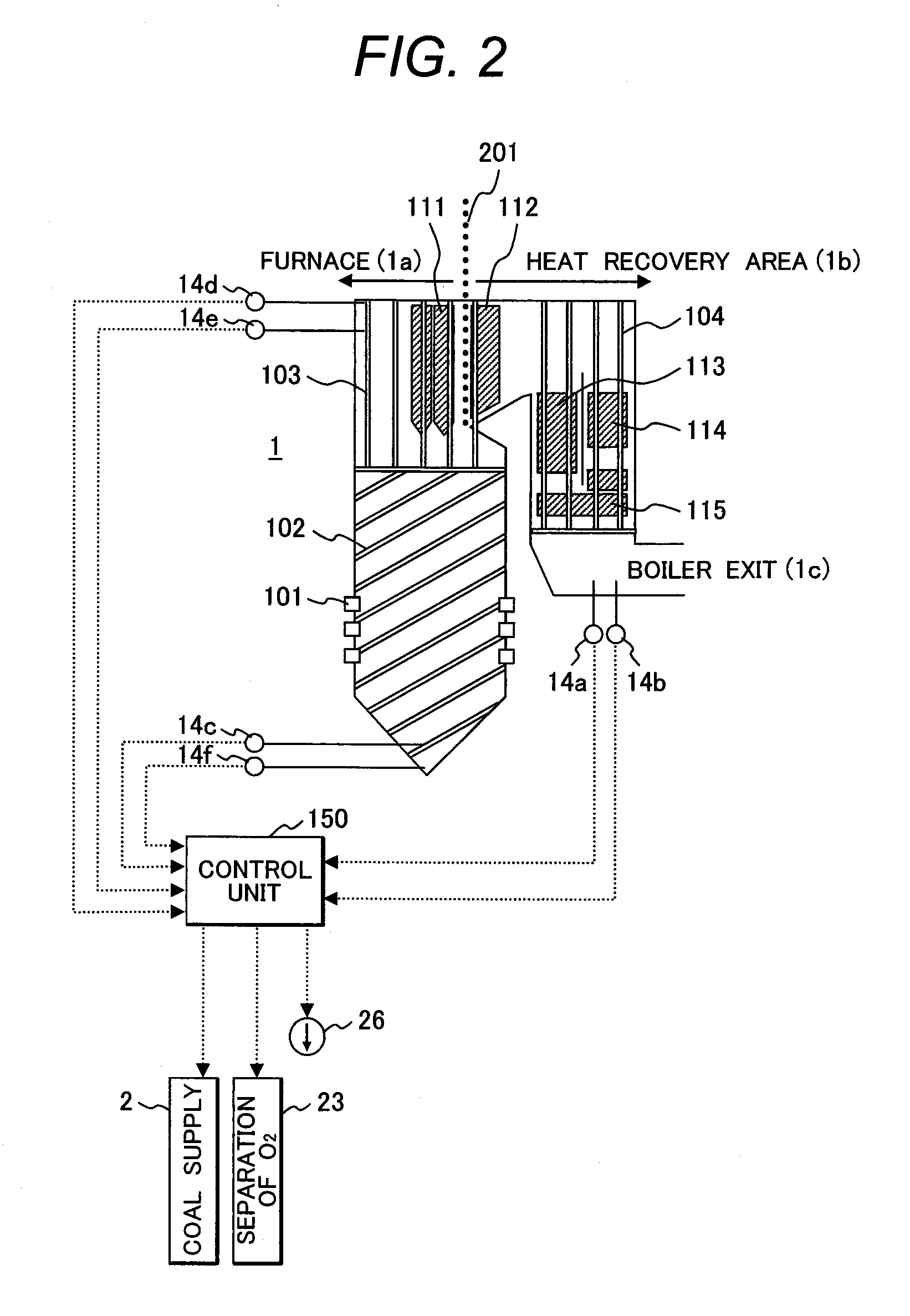
[0039]The oxyfuel boiler that is a first embodiment of the present invention and the control method for the oxyfuel boiler will be explained below by referring to FIGS. 1 to 5.

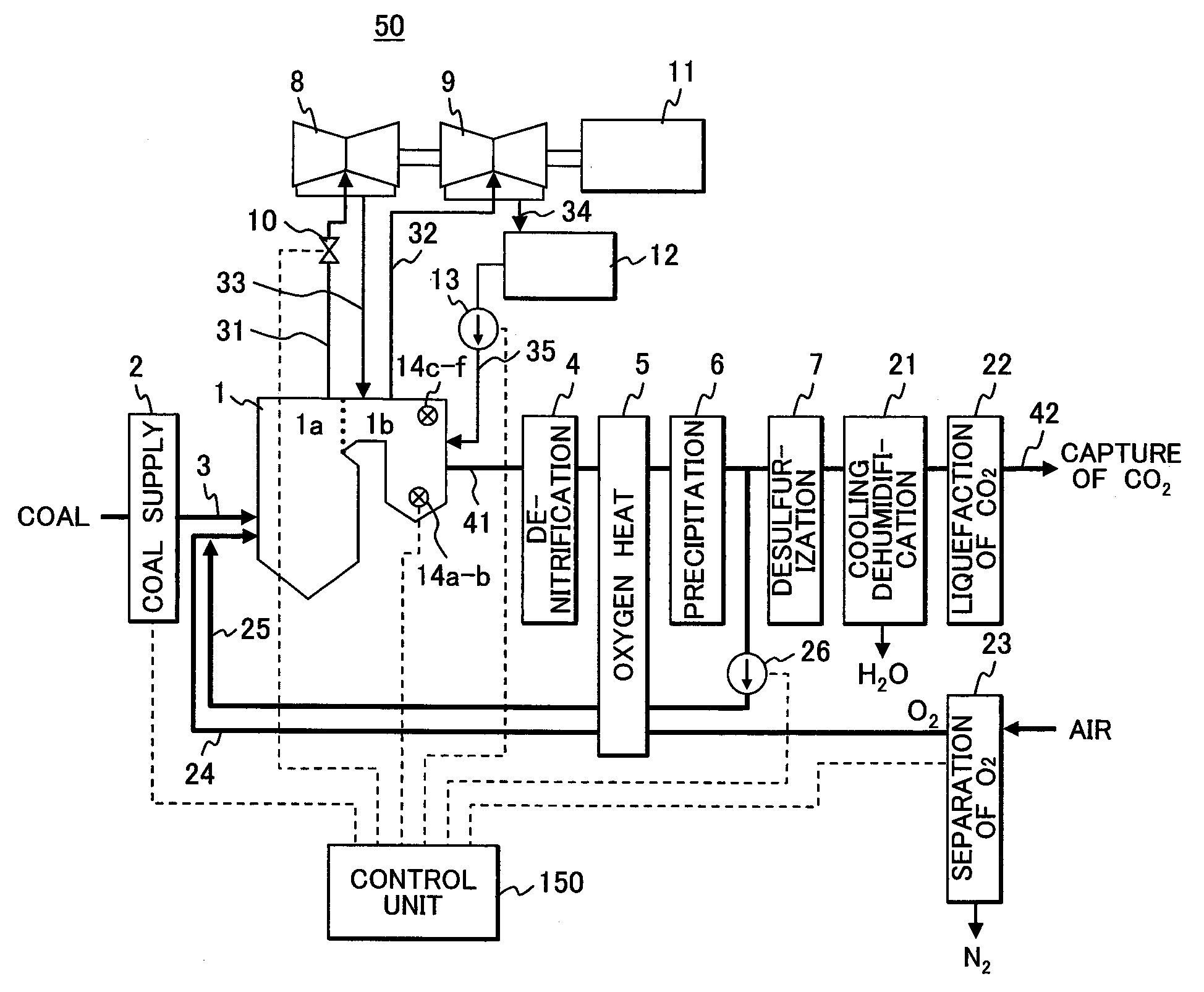
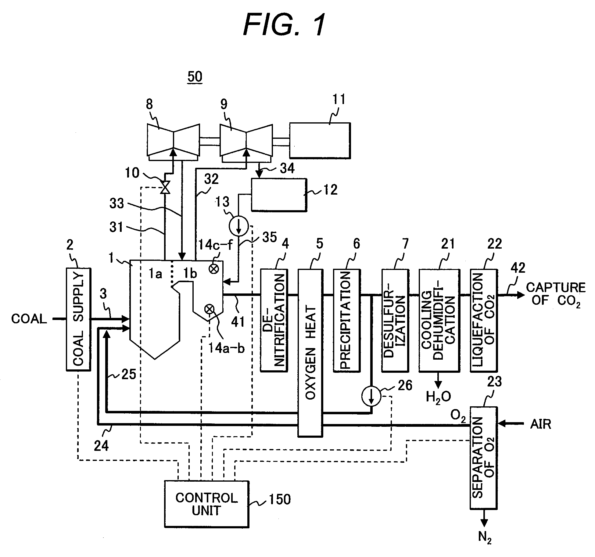
[0040]FIG. 1 is a schematic constitution showing the constitution of the coal thermal power plant suitable for CO2 capture having the oxyfuel boiler that is a first embodiment of the present invention.

[0041]The coal thermal power plant having the oxyfuel boiler which is a first embodiment of the present invention includes an oxyfuel boiler 1 for burning pulverized coal as fuel by oxygen separately supplied by the coal boiler. The oxyfuel boiler 1 has the same structure as that of an ordinary air-fuel boiler for burning pulverized coal as fuel by supplying air.

[0042]In the oxyfuel boiler 1, coal as fuel is pulverized to pulverized coal by a coal supply unit 2 and the pulverized coal is supplied to the oxyfuel boiler 1 via a coal supply system 3 from the coal supply unit 2 and is burnt together with oxygen separ...

embodiment 2

[0136]Next, the oxyfuel boiler which is a second embodiment of the present invention and the control method for the oxyfuel boiler will be explained below by referring to FIGS. 6 and 7.

[0137]FIG. 6 is a schematic cross sectional view showing the constitution of the coal thermal power plant suitable for CO2 capture having the oxyfuel boiler that is a second embodiment of the present invention.

[0138]The oxyfuel boiler 1 of the second embodiment of the present invention has a basic constitution substantially similar to that of the oxyfuel boiler 1 of the first embodiment of the present invention shown in FIGS. 1 to 5, so that the explanation of the portions of the constitution common to both will be omitted and only the different portions of the constitution will be explained below.

[0139]In the oxyfuel boiler 1 of the second embodiment of the present invention shown in FIGS. 6 and 7, compared with the oxyfuel boiler of the first embodiment shown in FIGS. 1 to 5, the constitution using ...

embodiment 3

[0154]Next, the oxyfuel boiler which is a third embodiment of the present invention and the control method for the oxyfuel boiler will be explained below by referring to FIGS. 8 and 9.

[0155]FIG. 8 is a schematic cross sectional view showing the constitution of the coal thermal power plant suitable for CO2 capture having the oxyfuel boiler which is a third embodiment of the present invention.

[0156]The oxyfuel boiler 1 of the third embodiment of the present invention has a basic constitution substantially similar to that of the oxyfuel boiler 1 of the second embodiment of the present invention shown in FIGS. 6 and 7, so that the explanation of the portions of the constitution common to both will be omitted and only the different portions of the constitution will be explained below.

[0157]In the oxyfuel boiler 1 of the third embodiment of the present invention shown in FIGS. 8 and 9, compared with the oxyfuel boiler of the second embodiment shown in FIGS. 6 and 7, with respect that in p...


PUM


Abstract

An oxyfuel boiler structured so as to mix oxygen separated from air with a part of exhaust gas branched from exhaust gas discharged from the boiler for generating vapor and supplying to a vapor demand facility by burning coal fuel, and supply the mixed gas to the boiler as an oxidizing gas for burning the coal, wherein an air separation unit for separating air and manufacturing oxygen from air, an oxygen supply system for leading the oxygen manufactured by the air separation unit to the oxyfuel boiler, a recirculation system for leading a part of exhaust gas branched from the exhaust gas discharged from the oxyfuel boiler to the oxyfuel boiler, and a recirculation fan for supplying the exhaust gas to the recirculation system are installed, respectively.

Description

CLAIM OF PRIORITY[0001]The present application claims priority from Japanese patent application serial No. 2009-165492, filed on Jul. 14, 2009, the content of which is hereby incorporated by reference into this application.BACKGROUND OF THE INVENTION[0002]1. Field of the Invention[0003]The present invention relates to a coal thermal power plant aiming at capturing CO2 and more particularly to an oxyfuel boiler suitable for capturing the CO2 of the coal thermal power plant and a control method for the oxyfuel boiler.[0004]2. Description of Related Art[0005]As a global warming countermeasure, the action of discharge reduction of CO2 (carbon dioxide) that is one of the green house gases is taken all over the world. The thermal power plant is one of the facilities discharging a large quantity of CO2 and particularly, the coal thermal power plant including a coal boiler of burning coal containing a large quantity of carbon and generating a large quantity of CO2 in combustion exhaust gas ...

Claims


Application Information

Patent Timeline
IPC IPC(8): F23J15/00F23N1/02F23B80/02
CPCF23C9/003F23C9/08F23C2202/30F23C2202/50Y02E20/344F23L7/007F23L2900/07001F23L2900/07005Y02E20/322F23C2900/09001Y02E20/32Y02E20/34
Inventor HAYASHI, YOSHIHARUSHIBATA, TSUYOSHITANIGUCHI, MASAYUKI
Owner HITACHI LTD
Why Eureka
Try Eureka