Discharge lamp lighting device, projector, and driving method of discharge lamp

a technology of discharge lamp and lighting device, which is applied in the direction of instruments, light sources, projectors, etc., can solve the problems of excessive evaporation of electrode material from the electrode tip portion, unstable arc origin, and reduced life of discharge lamp

Inactive Publication Date: 2011-01-20
SEIKO EPSON CORP
View PDF7 Cites 11 Cited by
  • Summary
  • Abstract
  • Description
  • Claims
  • Application Information

AI Technical Summary

Benefits of technology

Various embodiments of the disclosure provide a discharge lamp lighting device capable of suppressing th

Problems solved by technology

Such phenomena are not desirable because they reduce the brightness of a discharge lamp so that the lifespan of the discharge lamp is reduced.
If the projection of the electrode tip portion disappears, the arc origin becomes u

Method used


Image

  • Discharge lamp lighting device, projector, and driving method of discharge lamp
  • Discharge lamp lighting device, projector, and driving method of discharge lamp
  • Discharge lamp lighting device, projector, and driving method of discharge lamp

Examples


first embodiment

2. Discharge Lamp Lighting Device

(1) Configuration of a Discharge Lamp Lighting Device

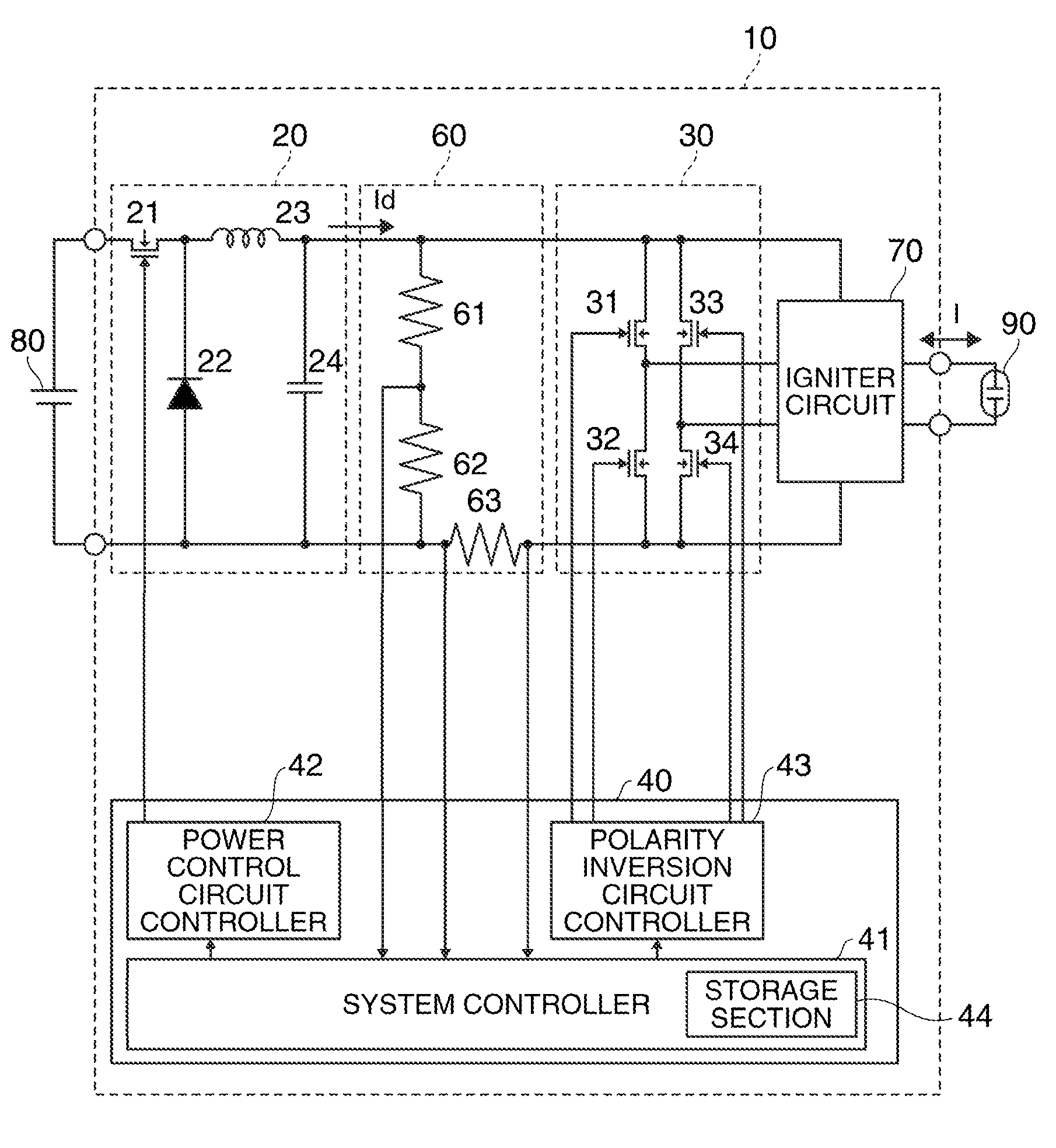
FIG. 3 shows an example of the circuit diagram of the discharge lamp lighting device according to the present embodiment.

The discharge lamp lighting device 10 includes a power control circuit 20. The power control circuit 20 generates driving electric power supplied to the discharge lamp 90. In the present embodiment, the power control circuit 20 is formed as a down chopper circuit to which power from a DC power supply 80 is input and from which a direct current Id is output after dropping the input voltage.

The power control circuit 20 may be configured to include a switching element 21, a diode 22, a coil 23, and a condenser 24. The switching element 21 may be formed by a transistor, for example. In the present embodiment, one end of the switching element 21 is connected to a positive voltage side of the DC power supply 80, and the other end is connected to a cathode terminal of the diode 22 and o...

second embodiment

3. Discharge Lamp Lighting Device

In the first embodiment, an example has been described in which the control unit 40 performs the first AC driving processing A1 at the fixed first frequency and performs the second AC driving processing A2 at the fixed second frequency. However, the control unit 40 may perform the first AC driving processing A1 and the second AC driving processing A2 by changing the first frequency in a first modulation pattern and changing the second frequency in a second modulation pattern different from the first modulation pattern.

FIGS. 8A and 8B are timing charts for explaining examples of the first and second modulation patterns. The vertical axis in FIG. 8A indicates the first frequency in the first modulation pattern, and the vertical axis in FIG. 8B indicates the second frequency in the second modulation pattern. In FIGS. 8A and 8B, the horizontal axis indicates a time. Moreover, when the driving current I is a direct current, the frequency is expressed as 0...

first modification

FIGS. 9A and 9B are timing charts for explaining other examples of the first and second modulation patterns. The vertical axis in FIG. 9A indicates the first frequency in the first modulation pattern, and the vertical axis in FIG. 9B indicates the second frequency in the second modulation pattern. In FIGS. 9A and 9B, the horizontal axis indicates a time. Moreover, when the driving current I is a direct current, the frequency is expressed as 0 Hz.

In the example shown in FIG. 9A, the first modulation pattern is a modulation pattern which includes periods b1-1, b1-2, b1-3, and b1-4, in each of which the first frequency is a fixed value, and in which a frequency-increasing change and a frequency-decreasing change are alternately repeated. In addition, the maximum value ΔF1 of a temporal change of the first frequency in the first modulation pattern is between the periods b1-1 and b1-2.

In the example shown in FIG. 9B, the second modulation pattern is a modulation pattern which includes pe...


PUM


Abstract

In at least one embodiment of the disclosure, a discharge lamp lighting device comprises a discharge lamp driving section and a control unit. The control unit alternately performs a first DC driving processing and a first AC driving processing in a first portion of the driving current. The control unit alternately performs a second DC driving processing and a second AC driving processing in a second portion of the driving current different from the first portion. The control unit performs the first AC driving processing and the second AC driving processing such that a frequency of a first alternating current and a frequency of a second alternating current have different values.

Description

CROSS-REFERENCEThe present application claims priority from Japanese Patent Application No. 2009-165355 filed on Jul. 14, 2009 which is hereby incorporated by reference in its entirety.BACKGROUNDDischarge lamps, such as high-pressure mercury lamps or metal halide lamps, have been used as light sources of a projector. In these discharge lamps, the shape of an electrode changes due to a drop in fusibility resulting from consumption of the electrode by discharge or progress of crystallization of the electrode according to an increase in cumulative lighting time. In addition, when a plurality of projections grow in an electrode tip portion or irregular consumption of the electrode body progresses by those described above, the arc origin moves or the arc length changes. Such phenomena are not desirable because they reduce the brightness of a discharge lamp so that the lifespan of the discharge lamp is reduced.In order to solve the problem, a discharge lamp lighting device that drives a d...

Claims


Application Information

Patent Timeline
IPC IPC(8): H05B41/36
CPCH05B41/2883G03B21/2053G03B21/2026H05B41/2928G03B21/14G03B21/2006H05B41/16
Inventor TERASHIMA, TETSUO
Owner SEIKO EPSON CORP
Why Eureka
Try Eureka