Method and apparatus for in-situ metrology of a workpiece disposed in a vacuum processing chamber

a vacuum processing chamber and workpiece technology, applied in the field of in-situ metrology of workpieces in vacuum processing chambers, can solve the problems of limited ocd metrology and impede the application of true in-situ metrology

Active Publication Date: 2011-01-20
APPLIED MATERIALS INC
View PDF5 Cites 17 Cited by
  • Summary
  • Abstract
  • Description
  • Claims
  • Application Information

AI Technical Summary

Problems solved by technology

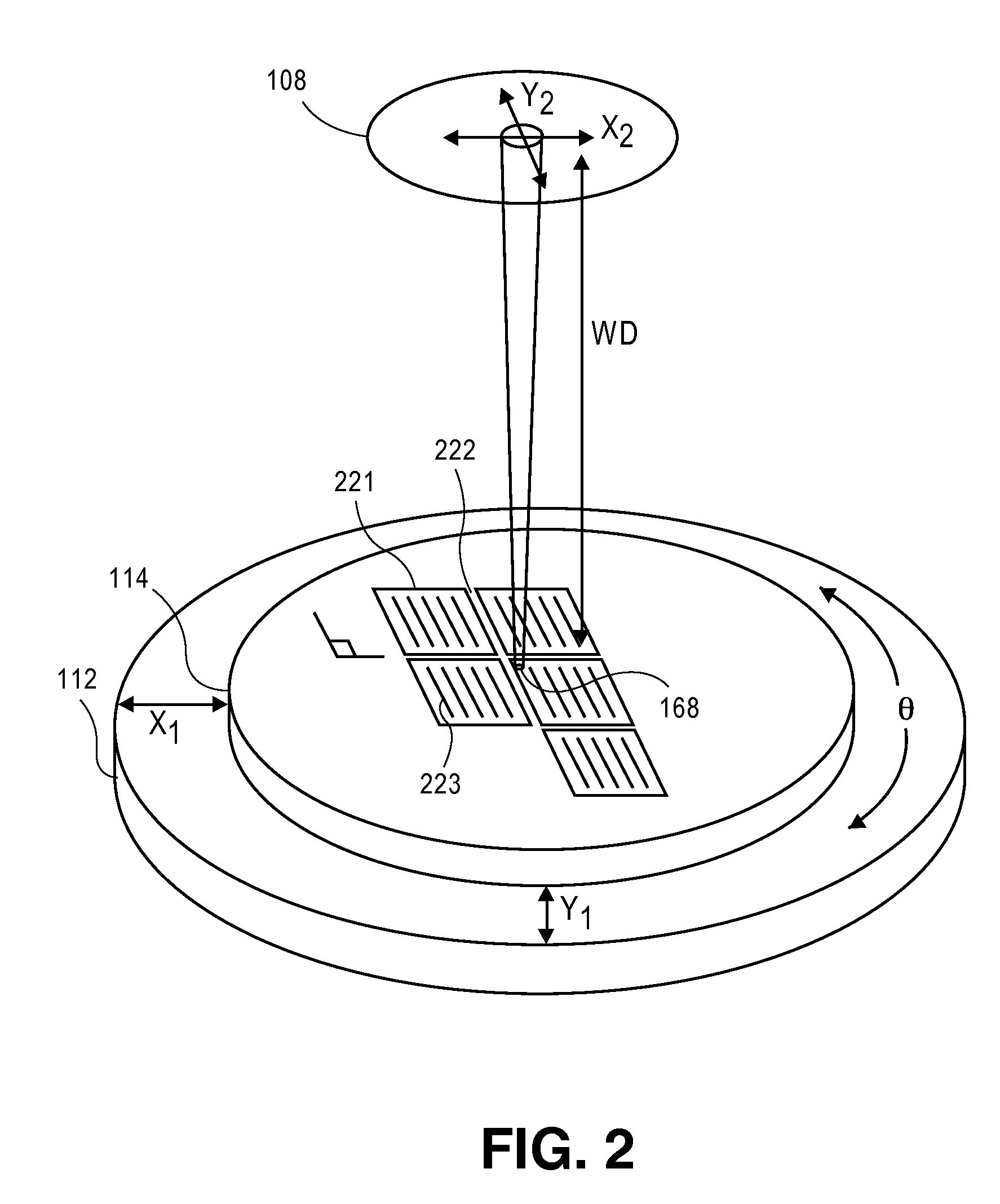
While critical dimensions of features may be deduced via OCD techniques, the difficulty in positioning an optical probe spot over a diffraction grating test structure with sufficient accuracy has hindered application of true in-situ metrology that can determine pre-etch, during-etch, or post-etch CD.
Therefore, to

Method used


Image

  • Method and apparatus for in-situ metrology of a workpiece disposed in a vacuum processing chamber
  • Method and apparatus for in-situ metrology of a workpiece disposed in a vacuum processing chamber
  • Method and apparatus for in-situ metrology of a workpiece disposed in a vacuum processing chamber

Examples


Embodiment Construction

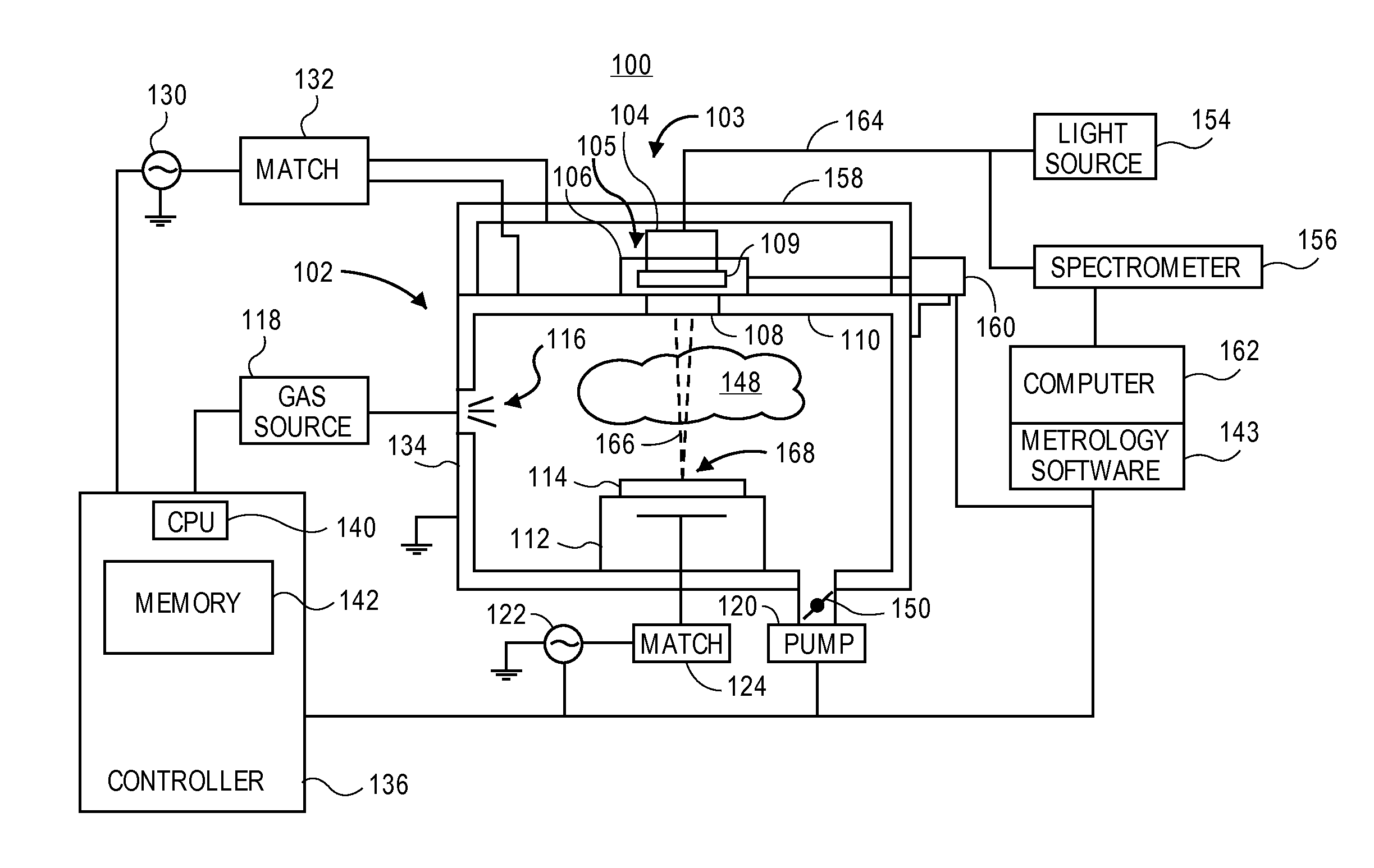
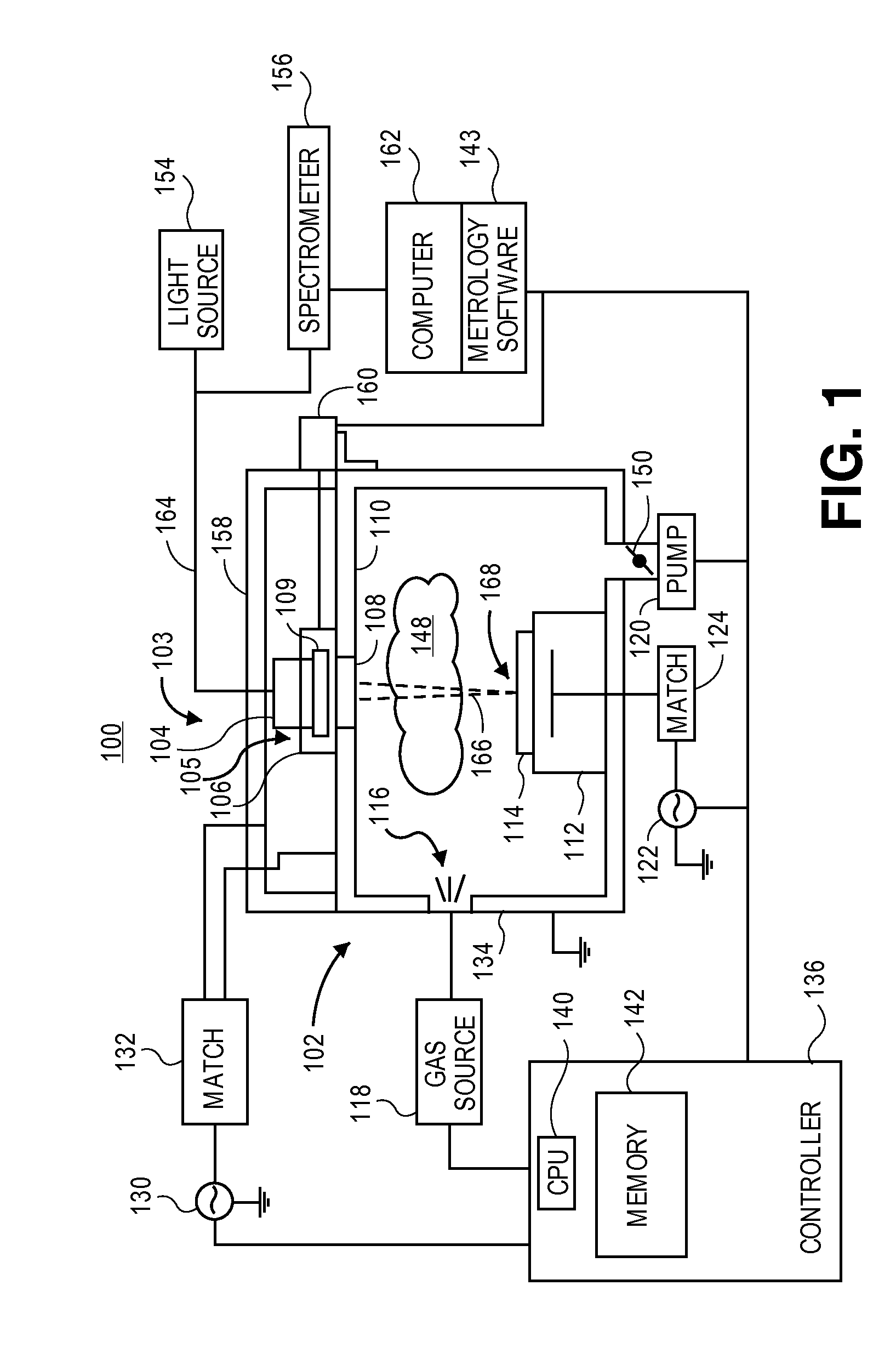
[0019]Embodiments of are described herein with reference to figures. However, particular embodiments may be practiced without one or more of these specific details, or in combination with other known methods, materials, and apparatuses. In the following description, numerous specific details are set forth, such as specific materials, dimensions and processes parameters etc. to provide a thorough understanding of the present invention. In other instances, well-known equipment design and process control techniques have not been described in particular detail to avoid unnecessarily obscuring the present invention. Reference throughout this specification to “an embodiment” means that a particular feature, structure, material, or characteristic described in connection with the embodiment is included in at least one embodiment of the invention. Thus, the appearances of the phrase “in an embodiment” in various places throughout this specification are not necessarily referring to the same e...


PUM


Abstract

A method and apparatus for in-situ metrology of a workpiece disposed in a vacuum processing chamber. The apparatus may include an optical assembly external to the processing chamber configured to focus a relatively large optical spot over a relatively large working distance to acquire a TE and TM spectra from a periodic array on the workpiece. The workpiece may be disposed in the processing chamber with an arbitrary orientation which is first determined via a reflectance measurement. TE and/or TM spectra may then be acquired by initiating a periodic triggering of a flash lamp based on the determined workpiece orientation to account for variation in placement of the workpiece within the processing chamber. The periodic array from which spectra are collected may be a memory array being fabricated in a semiconductor wafer.

Description

BACKGROUND[0001]1. Field[0002]Embodiments of the present invention relate to in-situ metrology in a vacuum processing chambers and more particularly to in-situ optical critical dimension (OCD) metrology (e.g., scatterometry) of a workpiece processed in the vacuum processing chamber.[0003]2. Discussion of Related Art[0004]Vacuum processing systems are ubiquitous in semiconductor fabrication. Certain vacuum processing chambers are configured to process a workpiece with a plasma or glow discharge. For example, a plasma etch process may pattern a feature in the workpiece based on a photo lithographically defined pattern. To reduce the feature sizes for a given photo lithographic technology node, a self-aligned double patterning (SADP) method may be employed where controlling a plasma etch process to a critical dimension and / or pitch is determinative. For example, a typical SADP processing includes trimming a mask from a first 1:1 line:space pitch to a 1:3 line:space pitch and then gener...

Claims


Application Information

Patent Timeline
IPC IPC(8): G01N21/47
CPCG03F7/70625G01B2210/56
Inventor DAVIS, MATTHEW F.LIAN, LEILILL, THORSTEN B.
Owner APPLIED MATERIALS INC
Why Eureka
Try Eureka