

Wavelength variable laser device, and method and program for controlling the same
a laser device and variable technology, applied in the direction of laser details, laser optical resonator construction, semiconductor lasers, etc., can solve the problems of high manufacturing cost, difficult to precisely butt joint between the active layer b>85/b> and the active layer b>86/b>, and reduce the cost of soa, increase yield, and simplify the manufacturing method
- Summary
- Abstract
- Description
- Claims
- Application Information
AI Technical Summary
Benefits of technology
Problems solved by technology
Method used
Image

Examples
Embodiment Construction
[0019]Hereinafter, exemplary embodiments of the invention will be described by referring to the drawings.
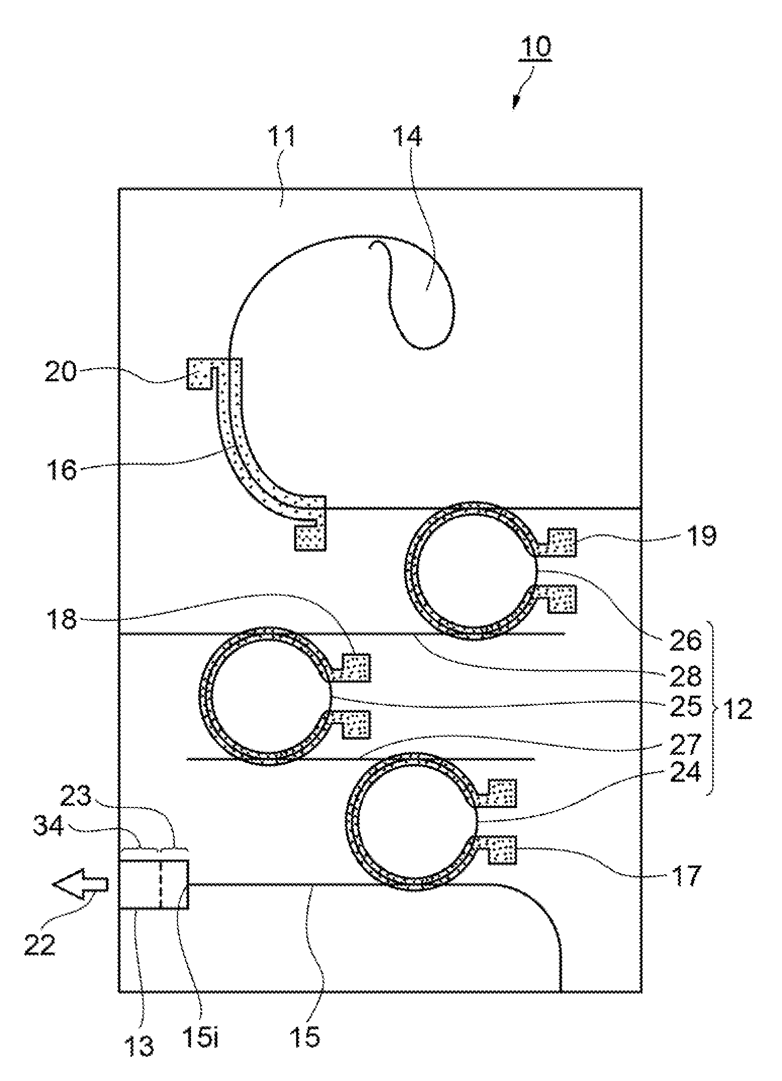
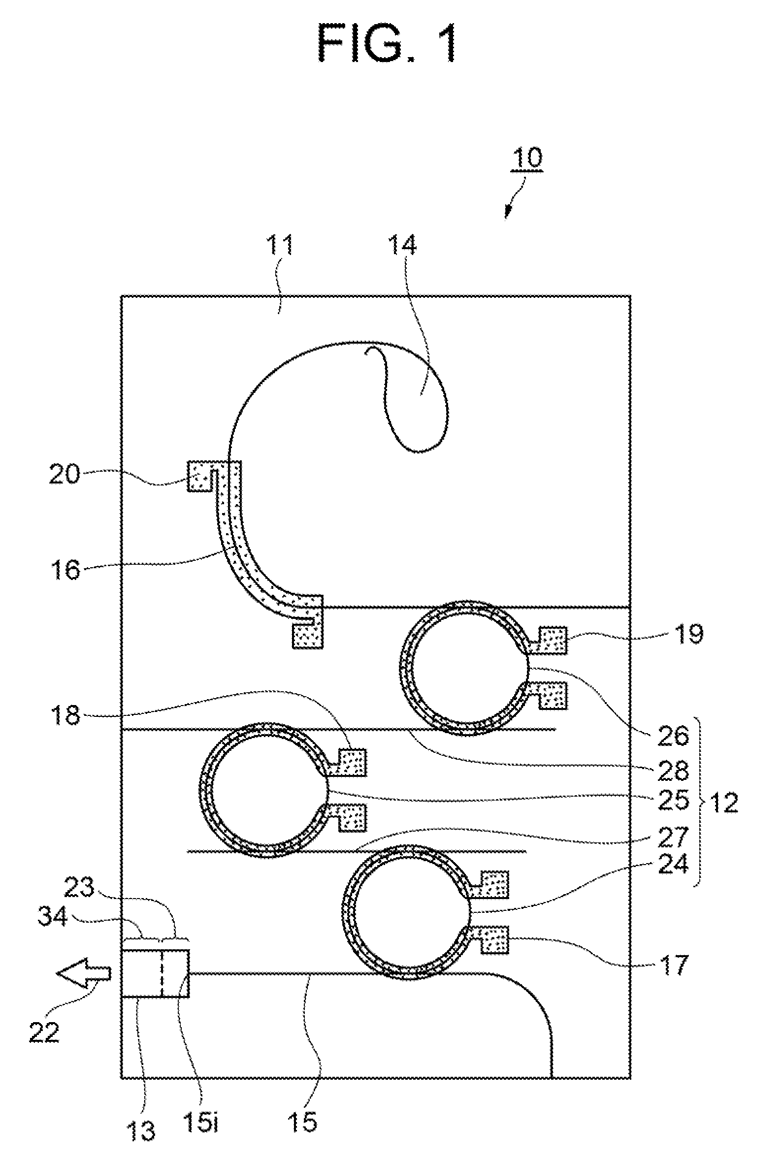
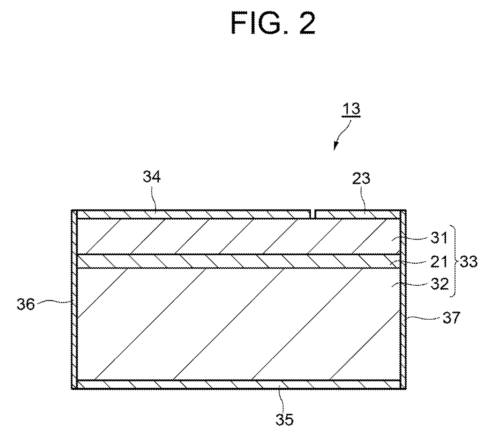
[0020]FIG. 1 is a plan view showing a first exemplary embodiment of a wavelength variable laser device according to the present invention. FIG. 2 is a schematic sectional view showing an SOA of the first exemplary embodiment. Hereinafter, explanations will be provided by referring to those drawings.
[0021]As shown in FIG. 1, a wavelength variable laser device 10 of the exemplary embodiment is characterized to include: an optical filter 12 formed on a PLC 11; an SOA 13 which supplies light to the optical filter 12; a light reflecting section 14 which returns the light transmitted through the optical filter 12 to the SOA 13 via the optical filter 12; optical waveguides 15 and 16 which are formed on the PLC 11 and connect the SOA 13, the optical filter 12, and the light reflecting section 14; wavelength variable sections 17, 18, and 19 which change the wavelength of the light transmi...
PUM
 Abstract
Description
Claims
Application Information