
Method for controlling a process and for monitoring the condition of process equipment, and an automation system

Active Publication Date: 2011-01-20
METSO AUTOMATION OY (FI)
View PDF6 Cites 12 Cited by
  • Summary
  • Abstract
  • Description
  • Claims
  • Application Information

AI Technical Summary

Benefits of technology

[0026]The integration of condition monitoring measurements, especially vibration measurements, in the automation system requires a totally novel type of I / O means, in which the sampling capacity and the signal transmission capacity of the I / O bus are designed to comply with the requirements of vibration measurements. In addition to the I / O rate and the bus capacity, the I / O means can be provided with an electronic connection suitable for vibration sensors, for example the power supply required by most commonly used acceleration sensors, as well as an efficient low-pass filter, to prevent the aliasing of high-frequency signal components to the frequency band under surveillance.
[0038]The costs are reduced. The number of required devices is reduced, since the I / O devices and software components for both the process control and the condition monitoring can be integrated in the same I / O unit and process station. Furthermore, it is possible to use the same user interface both for controlling the process and for monitoring its condition. In addition, the number of spare parts to kept in reserve is reduced. There is less configuration work for the system, because only one system needs to be configured. Moreover, the configuration is faster and more efficient, which brings savings in the maintenance costs.

Problems solved by technology

The objects are typically subjected to friction, which causes wearing and faults that can lead to a breakdown of the machine or the object monitored.
The reason for this is the fact that the automation system is not capable of operating in the dynamic range required by the condition monitoring system, which prevents the processing of condition monitoring signals directly in the automation system.
The I / O buses presently used in automation systems are not capable of transmitting large numbers of signals fast forward, but a typical I / O sampling frequency is 50 Hz.
This sampling frequency is insufficient for condition monitoring applications.
A problem in the use of separate automation and condition monitoring systems is that these systems do not communicate with each other without separate measures.
The transmission of data between the two systems is slow by applying methods of prior art.
It is slow to take measures that require fast, real-time control operations, such as to implement operations for protecting the process and its parts, for example to stop the apparatus in damage situations.
Another problem is caused by communication breakdowns between the two systems.
Consequently, the system is subjected to the same problems as were described above.
Furthermore, the use of field buses poses a substantial limitation on the quantity of data to be transmitted.
In practice, the capacity of the bus poses a substantial limit on the possibility to transfer such data quantities to the user interface for a more detailed analysis.

Method used


Image

  • Method for controlling a process and for monitoring the condition of process equipment, and an automation system
  • Method for controlling a process and for monitoring the condition of process equipment, and an automation system
  • Method for controlling a process and for monitoring the condition of process equipment, and an automation system

Examples


Embodiment Construction

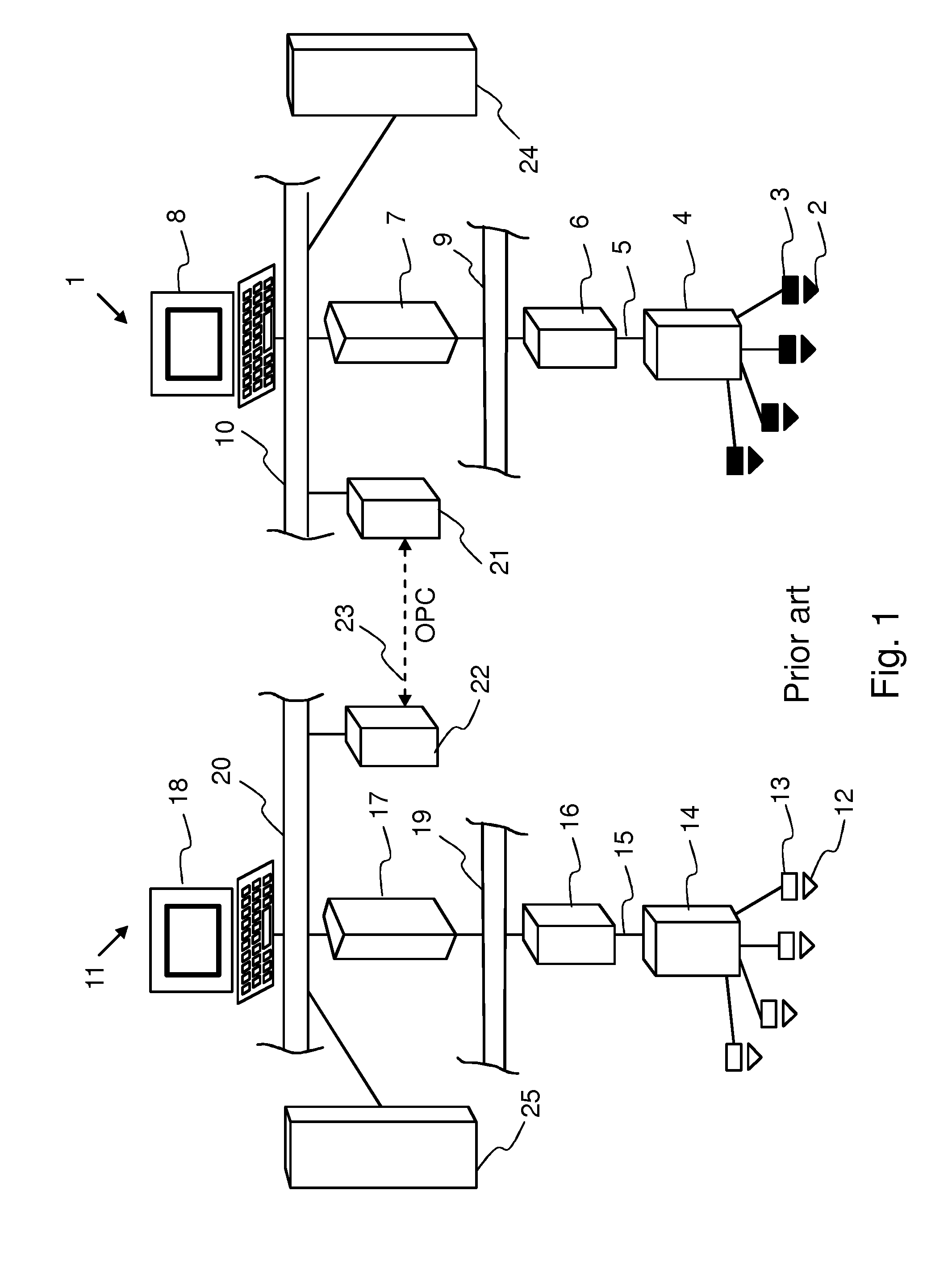
[0043]FIG. 1 has already been discussed above in connection with the description of prior art.

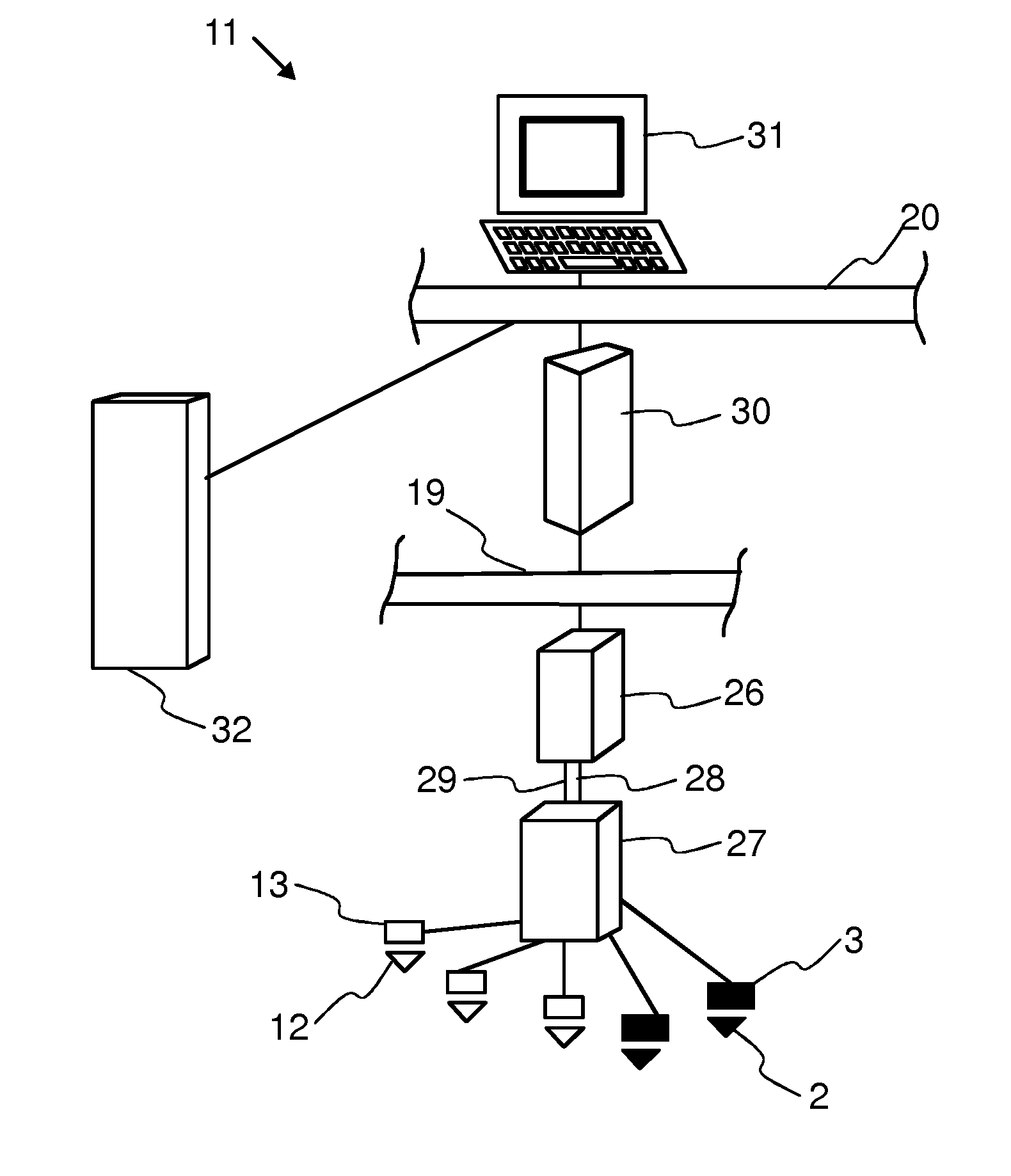
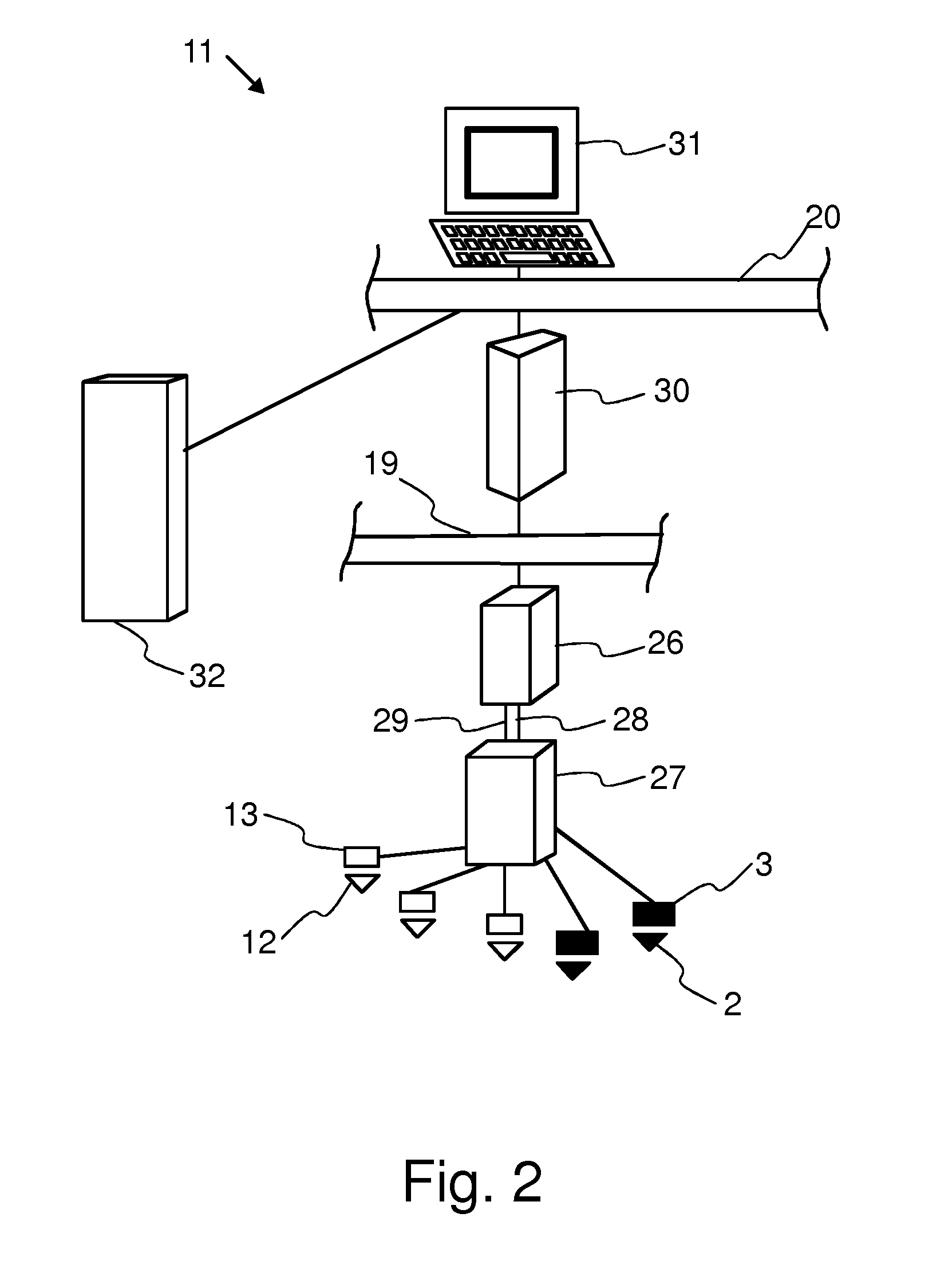
[0044]FIG. 2 shows an automation system with the built-in functionality of a condition monitoring system. The automation system is a so-called distributed control system that comprises several process stations, I / O devices and other servers, buses and stations; however, only one process station and the components connected to it are shown for the sake of clarity.

[0045]Process signals indicating the condition of a process 2 and measured by at least one sensor 3 installed for monitoring and controlling the process, are led into an I / O unit 27. The I / O unit 27 is provided with at least one I / O module 33 shown in FIG. 3 and arranged to process measurement signals with a low sampling frequency. The I / O module typically comprises at least one electronics card and the other components required for forming the I / O. The I / O module 33 is connected to a first I / O bus 28, via which the signals relating...


PUM


Abstract

An automation system and a method for controlling a process and for monitoring the condition of process equipment. The method comprises the steps of measuring process signals indicating the condition of the process by means of a first sensor; measuring condition monitoring signals indicating the condition of process components by means of a second sensor; processing the process signals by means of a first I / O module; processing the condition monitoring signals by means of a second I / O module; transmitting the processed process signals obtained from the first I / O module to a process station. The method also comprises the steps of transferring the processed condition monitoring signals obtained from the second I / O module to the same process station; and processing both the said processed process signals and the said processed condition monitoring signals by process station software in the said process station.

Description

FIELD OF THE INVENTION[0001]The invention relates to a method for controlling a process and for monitoring the condition of process equipment. The invention also relates to an automation system.BACKGROUND OF THE INVENTION[0002]A condition monitoring system is used for monitoring the condition of process equipment and parts thereof. In the system, signals from objects to be monitored are normally measured by various sensors and, for example, frequency spectra and various indices are computed from them to indicate the condition of the object to be monitored.[0003]Objects to be monitored typically include rotating shafts of various machines, bearings, or other rotating parts, such as cogged wheels of a gearbox, or turbine rotors, as well as various revolving objects in devices. Objects to be monitored also include, for example, rolls, pumps, blowers, screens, grinders, barking drums, mixers, wires, and felts in the manufacturing process of paper and pulp. The objects are typically subj...

Claims


Application Information

Patent Timeline
IPC IPC(8): G05B13/02G06F15/00G01K13/00G06F19/00G01L9/00G01F1/00G01P15/00
CPCG05B2219/33299G05B19/0423
Inventor MUSTONEN, HARRILEHIKOINEN, AKIBORG, ALE
Owner METSO AUTOMATION OY (FI)
Learn More