Method of operating gasification facility

a gasification facility and gasification technology, applied in the direction of lighting and heating apparatus, combustion types, sustainable manufacturing/processing, etc., can solve the problems of increasing the cost of purging, the need for bed material heating, and the cost of fuel consumption, so as to reduce the cost of heating the bed material upon cold startup, and achieve effective and inexpensive purging

Active Publication Date: 2011-01-27
IHI CORP
View PDF5 Cites 16 Cited by
  • Summary
  • Abstract
  • Description
  • Claims
  • Application Information

AI Technical Summary

Benefits of technology

[0028]According to a method of operating a gasification facility, upon cold startup of the gasification facility, a fluidizing air is supplied to the combustion furnace to fluidize a combustion-furnace fluidized bed while a preheating fuel such as LNG, LPG or light oil is supplied to the combustion furnace to preheat the combustion-furnace fluidized bed up to an autoignition temperature of coal; the coal is then charged into the combustion furnace to heat the combustion-furnace fluidized bed with the combustion of the coal; and the bed material is then circulated between the combustion and gasification furnaces for heating, so that the used amount of the expensive preheating fuel such as LNG, LPG or light oil may be limited to a small amount only for preheating the combustion-furnace fluidized bed of the combustion furnace and, therefore, the cost for heating the bed material upon cold startup may be considerably reduced.
[0029]Upon startup of the gasification facility, a steam from an exhaust heat recovery boiler in heat exchange with an exhaust gas from the combustion furnace is supplied to the gasification furnace to purge the gasification furnace and a lead-out passage for a produced gas with the steam, so that the gasification furnace and the lead-out passage for the produced gas may be effectively and inexpensively purged with the steam utilizing the exhaust heat.
[0030]Upon shutdown of the gasification facility, the steam is continued to be produced in the exhaust heat recovery boiler and is supplied to the gasification furnace to purge the gasification furnace and the lead-out passage for the produced gas with the steam, so that the gasification furnace and the lead-out passage for the produced gas may be effectively and inexpensively purged with the steam utilizing the exhaust heat even when the gasification facility is stopped.

Problems solved by technology

It is, however, problematic that a considerable cost is required for the heating of the bed material since a large amount of fuel such as LNG, LPG or light oil is needed for heating a large amount of bed material housed in gasification and combustion furnaces with large capacities as in the two-tower gasification facility up to a temperature which enables the gasification of raw material and such fuel is relatively expensive.
It is, however, problematic that cost for the purge increases since the purge of the gasification furnace generally requires an amount of inert gas about five times greater than the capacity of the gasification furnace and therefore a large nitrogen producer is required.
Thus, for a gasification facility, a technique has been desired to be developed which can reduce the cost required for heating the bed material especially upon cold startup of the gasification facility and which can effectively and inexpensively perform an operation of purging a gasification furnace and a lead-out passage for produced gas; however, currently such a technique has not been proposed.

Method used


Image

  • Method of operating gasification facility
  • Method of operating gasification facility
  • Method of operating gasification facility

Examples


Embodiment Construction

[0066]An embodiment of the invention will be described with reference to the accompanying drawings.

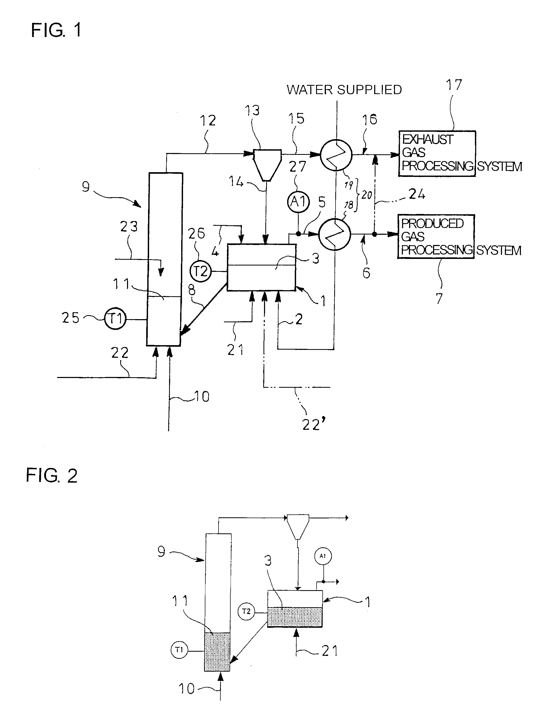
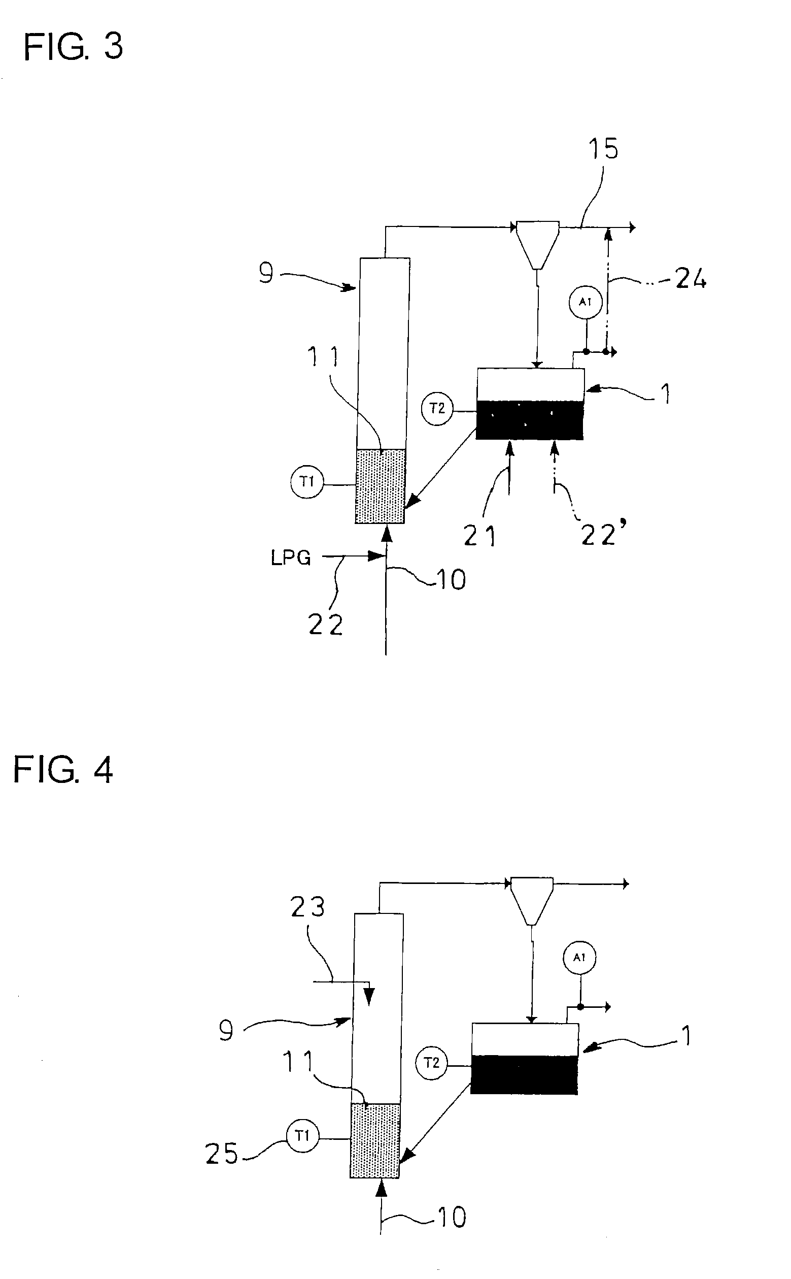
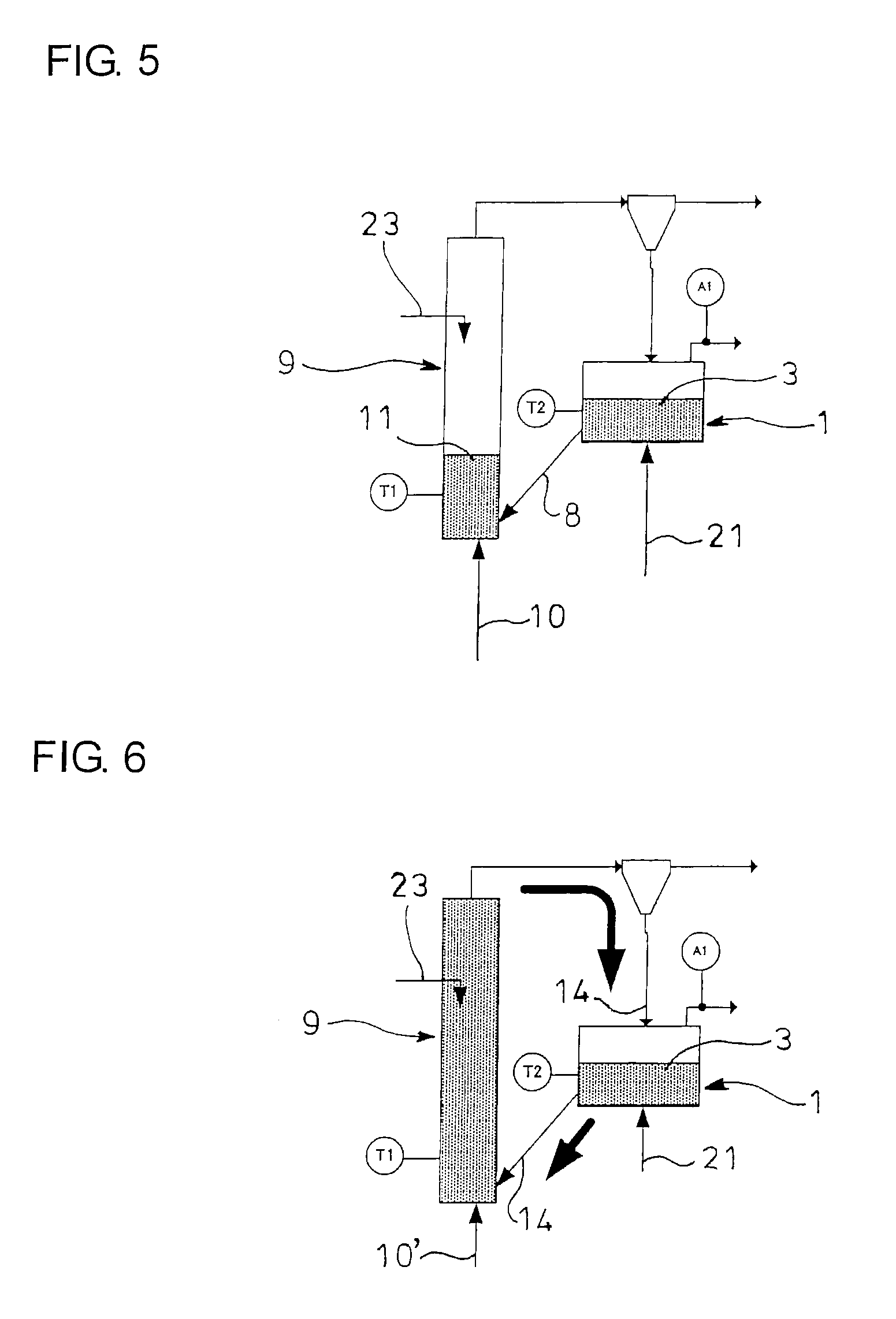
[0067]FIG. 1 shows a two-tower gasification facility which embodies the invention. The gasification facility comprises gasification and combustion furnaces 1 and 9. In the gasification furnace 1, steam 2 is supplied from below from an air diffuser (not shown) to form a gasification-furnace fluidized bed 3 of bed material (such as silica sand or limestone) where a raw material 4 (such as coal, biomass or tire chips) charged from above is gasified to produce a produced gas and unreacted char. The produced gas 5 produced by the gasification furnace 1 is supplied through a lead-out passage 6 to a produced gas processing system 7. A mixture 8 of the unreacted char produced by the gasification furnace 1 with the bed material is introduced into the combustion furnace 9 by overflow.

[0068]In the combustion furnace 9, fluidizing air 10 is supplied from below from an air diffuser (not shown) to f...


PUM

PropertyMeasurementUnit
autoignition temperatureaaaaaaaaaa
temperatureaaaaaaaaaa
autoignition temperatureaaaaaaaaaa

Abstract

Upon cold startup of a gasification facility, a fluidized air 10 is supplied to a combustion furnace 9 to fluidize a combustion-furnace fluidized bed 11 while a preheating fuel 22 is supplied to the combustion furnace to preheat the fluidized bed 11 up to an autoignition temperature of coal. Then, a coal 23 is charged to the combustion furnace 9 to heat the fluidized bed 11 and bed material is circulated between the combustion and gasification furnaces 9 and 1 for heating. Upon startup and shutdown of the gasification facility, steam 2 from an exhaust heat recovery boiler 20 in heat exchange with an exhaust gas 15 from the combustion furnace 9 is supplied to the gasification furnace 1 to purge the gasification furnace 1 and a lead-out passage 6 with the steam 2 utilizing the exhaust heat.

Description

TECHNICAL FIELD[0001]The present invention relates to a method of operating a gasification facility.BACKGROUND ART[0002]Conventionally, a variety of gasification facilities have been proposed. For example, there is a so-called two-tower circulating fluidized bed gasification facility comprising gasification and combustion furnaces (see Patent Literature 1).[0003]In the gasification furnace constituting the two-tower gasification facility, steam is fed from below to provide a fluidized bed of bed material (such as silica sand or limestone) for gasification of a raw material (such as coal, biomass or tire chips) charged from above to thereby produce a produced gas and unreacted char. The produced gas produced in the gasification furnace is taken out through a lead-out passage to outside, and a mixture of the unreacted char produced in the gasification furnace with the bed material is introduced into the combustion furnace through a lead-in pipe.[0004]In the combustion furnace constitu...

Claims


Application Information

Patent Timeline
Patent Type & Authority Applications(United States)
IPC IPC(8): C10J3/48
CPCY02E20/18F23G2201/304C10J2300/093C10J2300/0956C10J2300/0976C10J2300/0993C10J2300/1637C10J2300/1807F23G2201/40F23G2203/501F23G2203/503F23G2209/281F23G5/0276F23G5/30F23G5/50F23G7/12C10J3/463Y02P20/129Y02P20/10
Inventor NUKUMI, HISANORIKATAGIRI, TOMOYUKI
Owner IHI CORP
Why Eureka
Try Eureka