Cooling structure for gas turbine combustor

a technology of cooling structure and gas turbine, which is applied in the direction of efficient propulsion technology, machines/engines, light and heating apparatus, etc., can solve the problems of increasing the emission of nox, and achieve the effect of facilitating cooling at the center of the cell and increasing the heat transfer surface area

Inactive Publication Date: 2011-01-27
KAWASAKI HEAVY IND LTD
View PDF17 Cites 41 Cited by
  • Summary
  • Abstract
  • Description
  • Claims
  • Application Information

AI Technical Summary

Benefits of technology

[0019]In a still further embodiment of the present invention, a stand-alone rib may be provided at a center of each of cells defining the honeycomb construction and separate from each of sides of the honeycomb construction. The use of the stand-alone ribs at the respective centers of the cells is advantageous in that since the stand-alone ribs are separate from and independent of the ribs, increase of the heat transfer surface area can be brought about by the stand-alone ribs at the respective centers of the cells of the honeycomb construction to such an extent as to result in generation of turbulent flows downstream of the stand-alone ribs to thereby stir the compressed air. Therefore, cooling at the centers of the cells can be facilitated and, hence, the uniform convection cooling effect can be obtained over the entire outer peripheral surface of the combustion liner. It is to be noted that the shape of each of the stand-alone ribs may be a cylindrical shape or a polygonal column shape, but the present invention may not necessarily be limited thereto.

Problems solved by technology

However, increase of the flame temperature tends to result in an increase of the emission of NOx and, therefore, to reduce the emission of NOx, it is necessary to suppress the increase of the flame temperature by increasing the amount of air used for combustion.

Method used


Image

  • Cooling structure for gas turbine combustor
  • Cooling structure for gas turbine combustor
  • Cooling structure for gas turbine combustor

Examples


first embodiment

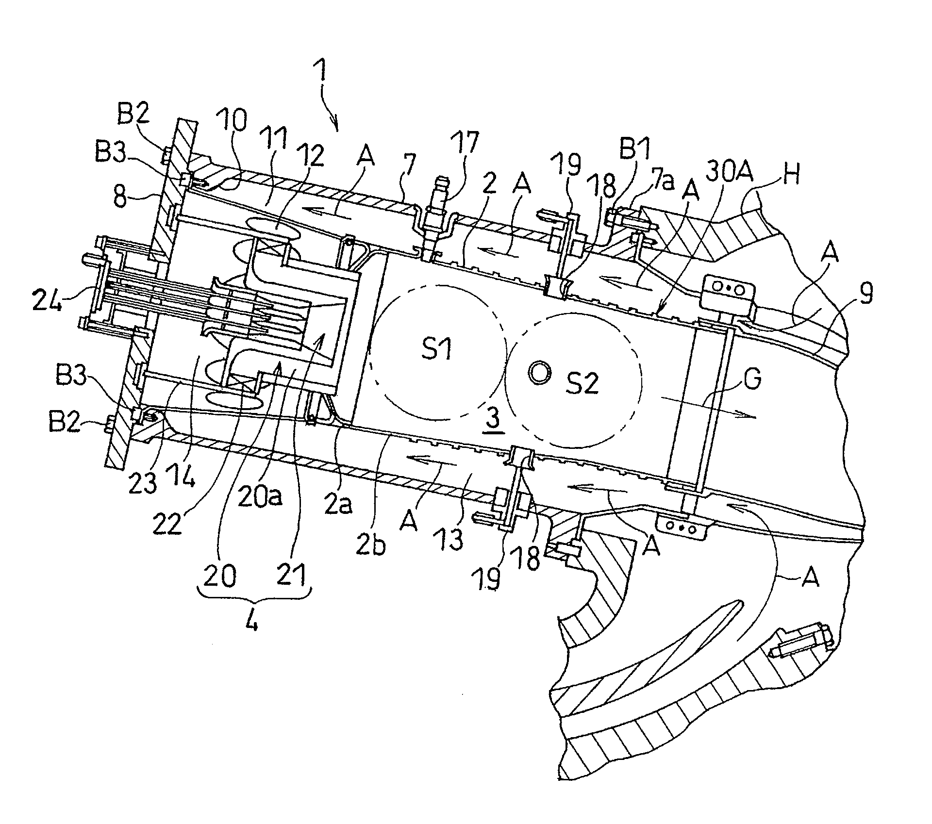
[0036]FIG. 1 illustrates a gas turbine combustor 1 according to the present invention in a fragmentary longitudinal sectional representation. The gas turbine engine has three principal components including a compressor, a gas turbine combustor 1 and a turbine and is so designed that a compressed air A supplied from the compressor can be mixed with fuel within the gas turbine combustor 1, in which combustion of the mixture of the compressed air with the fuel takes place to generate a combustion gas G of high temperature and high pressure. The combustion gas G is in turn supplied to the turbine to provide a drive power. In this gas turbine engine the compressor is driven by the turbine. Such a load as, for example, an aircraft rotor or a power generator is driven by an output of the gas turbine engine.

[0037]The gas turbine combustor 1 is generally employed in a plural number in one gas turbine engine and those gas turbine combustors 1 are disposed around the rotational axis of the eng...

second embodiment

[0052]FIG. 6 illustrates a schematic perspective view of a portion of a heat transfer enhancement structure 30B formed on the combustion liner 2 of the gas turbine combustor according to the present invention. The heat transfer enhancement structure 30B is substantially similar to the heat transfer enhancement structure 30A according to the previously described embodiment as far as the vertical walls 29B of the equilateral hexagonal shape are arranged next to each other, but differs from the heat transfer enhancement structure 30A in that two ribs 32C of the six ribs depicting the equilateral hexagonal shape, which are opposed to each other and extends parallel to the direction of flow of the compressed air A are so formed as to protrude beyond the remaining, slanted ribs 32B in a direction away from the peripheral surface 2c of the combustion liner 2, that is, as to have a height larger than that of each of the slanted ribs 32B.

[0053]With the heat transfer enhancement structure 30B...

fourth embodiment

[0056]FIG. 8 illustrates a schematic side view of that portion of the heat transfer enhancement structure, now identified by 30C, which is formed on the outer peripheral surface 2c of the combustion liner 2 in the gas turbine combustor according to the present invention, as viewed from a radial direction of the combustion liner 2. The heat transfer enhancement structure 30C is of a honeycomb construction including a multiplicity of rhombic cells 31C, each arranged next to each other and bound by a corresponding vertical wall 29C. In the heat transfer enhancement structure 30C, at least two vertexes opposed each other, forming one vertex pair out of two vertex pairs of the square shape, are opposed to each other on the outer peripheral surface 2c of the combustion liner 2 in a direction parallel to the direction of flow of the compressed air A. As a matter of course, each of the four ribs 32D forms slanted relative to the direction of flow of the compressed air A. Also, those four sl...


PUM


Abstract

To provide a gas turbine combustor having an improved cooling structure effective to efficiently suppress a possible occurrence of buckling in the combustion liner while exhibiting a convection cooling effect to the combustion liner, the gas turbine combustor includes a combustion liner having a combustion chamber defined therein and an outer peripheral surface forming a path of a compressed air, and a heat transfer enhancement structure provided on the outer peripheral surface of the combustion liner. The heat transfer enhancement structure referred to above is of a honeycomb construction defined by ribs protruding outwardly from the outer surface of the combustion liner. The honeycomb construction may be of a geometry in which hexagonal shapes, rhombic shapes, parallelogrammic shapes, bent rectangular shapes or triangular shapes are deployed next to each other.

Description

CROSS REFERENCE TO THE RELATED APPLICATION[0001]This application is a continuation application, under 35 U.S.C. §111(a), of international application No. PCT / JP2008 / 004008, filed Dec. 26, 2008, which claims priority to Japanese patent application No. 2008-092813, filed Mar. 31, 2008, the disclosure of which is incorporated by reference in its entirety into this application.BACKGROUND OF THE INVENTION[0002]1. (Field of the Invention)[0003]The present invention generally relates to a gas turbine combustor and, more particularly, to an improved cooling structure used in the gas turbine combustor for cooling a combustion liner with a compressed air flowing outside such combustion liner.[0004]2. (Description of the Related Art)[0005]In the gas turbine engine, in order to improve the turbine efficiency, a tendency is found in recent years to set the temperature of the combustion gas at a turbine inlet to be high. However, increase of the flame temperature tends to result in an increase of...

Claims


Application Information

Patent Timeline
Patent Type & Authority Applications(United States)
IPC IPC(8): F02C1/00
CPCF05B2250/283F05B2260/222F05B2260/2241F23R3/005F23R2900/03045Y02T50/675F23R3/002Y02T50/60
Inventor IWASAKI, HIDEKAZU
Owner KAWASAKI HEAVY IND LTD
Why Eureka
Try Eureka