Air conditioner for vehicle with heat pump cycle

Inactive Publication Date: 2011-01-27
DENSO CORP
View PDF10 Cites 134 Cited by
  • Summary
  • Abstract
  • Description
  • Claims
  • Application Information

AI Technical Summary

Benefits of technology

[0020]According to another aspect of the present invention, an air conditioner for a vehicle includes a vapor compression refrigeration cycle including an outdoor heat exchanger configured to perform heat exchange between refrigerant and air outside of a vehicle compartment, and an indoor heat exchanger configured to perform heat exchange between the refrigerant and air to be blown into the vehicle compartment. The vapor compression refrigerant cycle is configured to be switchable between a heat pump cycle in which a heat amount absorbed from the outdoor heat exchanger is radiated to the indoor heat exchanger to heat air to be blown into the vehicle compartment, and a cooler cycle in which a heat amount absorbed from the indoor heat exchanger is radiated to the outdoor heat exchanger. In the air conditioner, a controller causes the vapor compression refrigeration cycle to be operated as the cooler cycle so as to perform a defrosting control of the outdoor heat exchanger, when the controller determines that the outdoor heat exchanger is frosted. Furthermore, in a case where the controller determines that the outdoor heat exchanger is frosted, the controller prohibits the defrosting control when performing- a pre-air conditioning control which starts air conditioning in the vehicle compartment before the passenger rides on the vehicle, and performs the defrosting control when the pre-air conditioning control is not performed. Thus, it can prevent heating of the vehicle compartment from being lowered in the pre-air conditioning control.
[0021]According to another aspect of the present invention, an air conditioner for a vehicle includes a vapor compression refrigeration cycle including an outdoor heat exchanger configured to perform heat exchange between refrigerant and air outside of a vehicle compartment, and an indoor heat exchanger configured to perform heat exchange between the refrigerant and air to be blown into the vehicle compartment. The vapor compression refrigerant cycle is configured to be switchable between a heat pump cycle in which a heat amount absorbed from the outdoor heat exchanger is radiated to the indoor heat exchanger to heat air to be blown into the vehicle compartment, and a cooler cycle in which a heat amount absorbed from the indoor heat exchanger is radiated to the outdoor heat exchanger. A controller configured to control the vapor compression refrigeration cycle causes the vapor compression refrigeration cycle to be operated as the cooler cycle so as to perform a defrosting control of the outdoor heat exchanger, when the controller determines that the outdoor heat exchanger is frosted. Furthermore, the outdoor heat exchanger is arranged to be tilted with respect to a vertical direction such that a flow direction of air passing through the outdoor heat exchanger is toward a lower side than a horizontal direction. In this case, water or ice included in the water can easily fall downwardly, thereby effectively reducing the defrosting time.
[0022]According to another aspect of the present invention, an air conditioner for a vehicle includes a vapor compression refrigeration cycle including an outdoor heat exchanger configured to perform heat exchange between refrigerant and air outside of a vehicle compartment, and an indoor heat exchanger configured to perform heat exchange between the refrigerant and air to be blown into the vehicle compartment. The vapor compression refrigerant cycle is configured to be switchable between a heat pump cycle in which a heat amount absorbed from the outdoor heat exchanger is radiated to the indoor heat exchanger to heat air to be blown into the vehicle compartment, and a cooler cycle in which a heat amount absorbed from the indoor heat exchanger is radiated to the outd

Problems solved by technology

However, in the vehicle air conditioner, when the heat pump cycle is switched to the cooler cycle so that the defrosting of the outdoor heat exchanger of the heat pump cycle is performed, if the defrosting time is long, a heating feeling given to a passenger in the vehicle compartment is deteriorated.
Furthermore, in the vehicle air conditioner described in JP-A-2002-174474, when an engine operation is not necessary as a driving source of a vehicle traveling, such as in a case of an idling-stop vehicle or a hybrid car, it is difficult to obtain a sufficient heating feeling

Method used


Image

  • Air conditioner for vehicle with heat pump cycle
  • Air conditioner for vehicle with heat pump cycle
  • Air conditioner for vehicle with heat pump cycle

Examples


Example

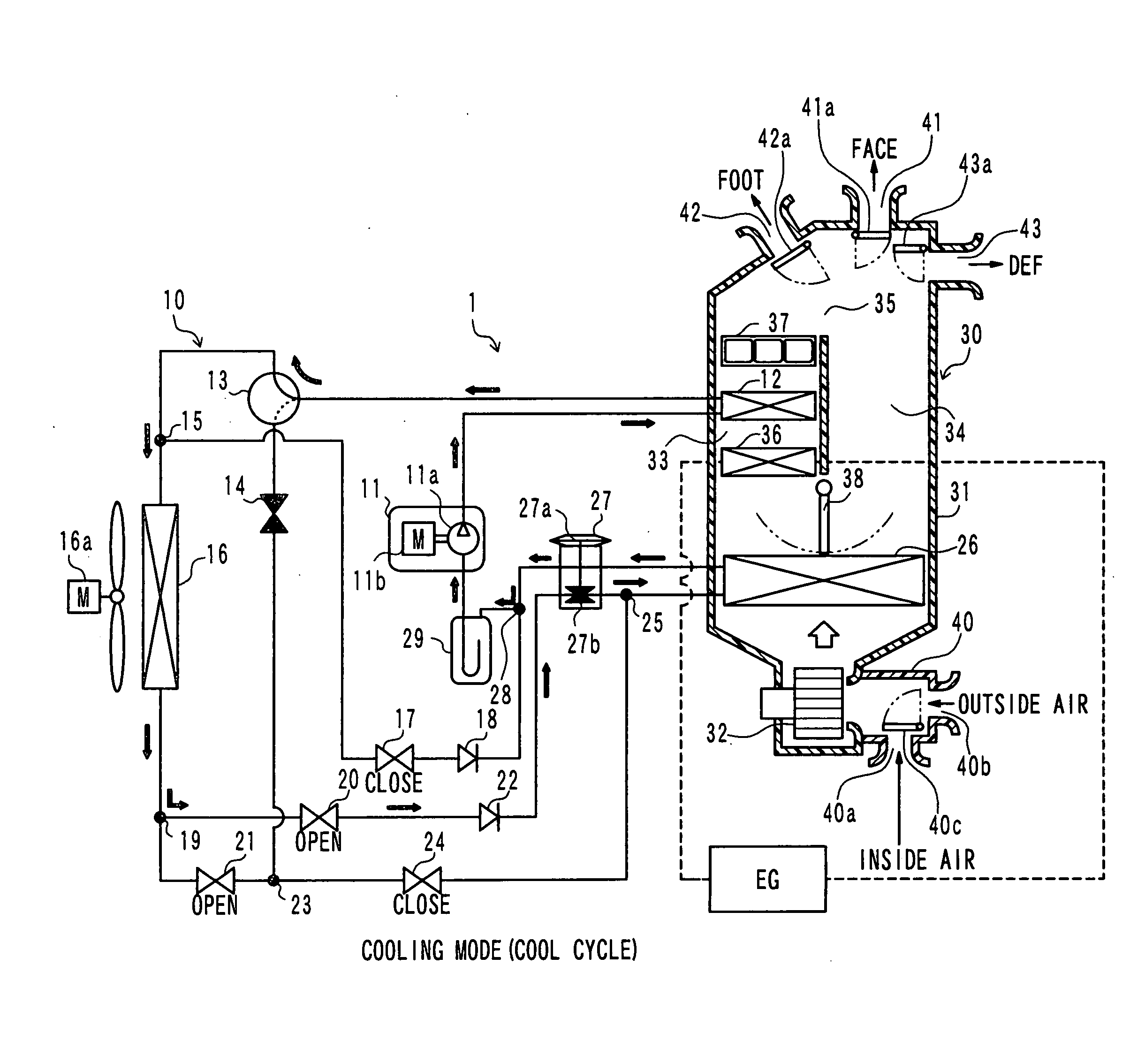
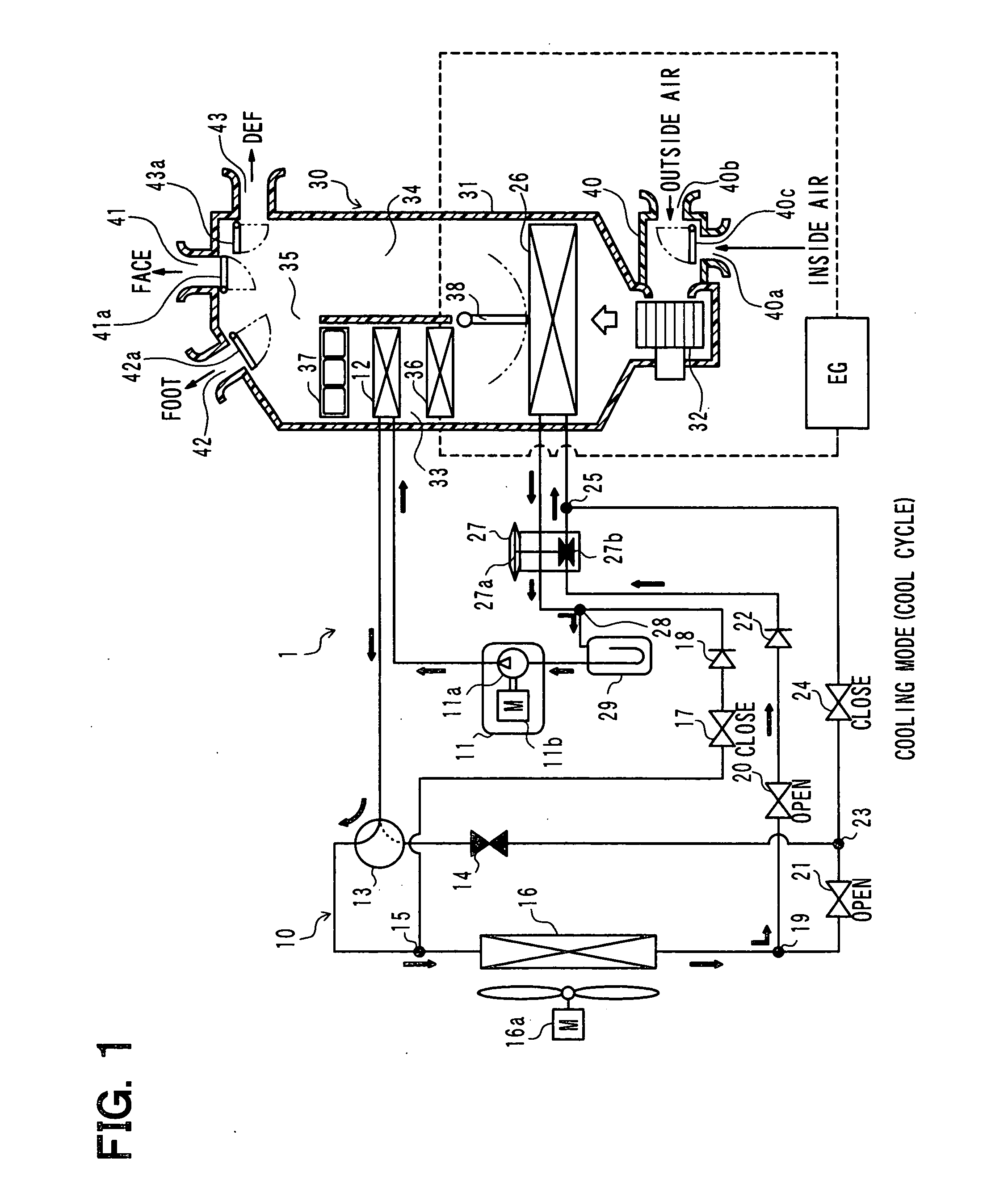
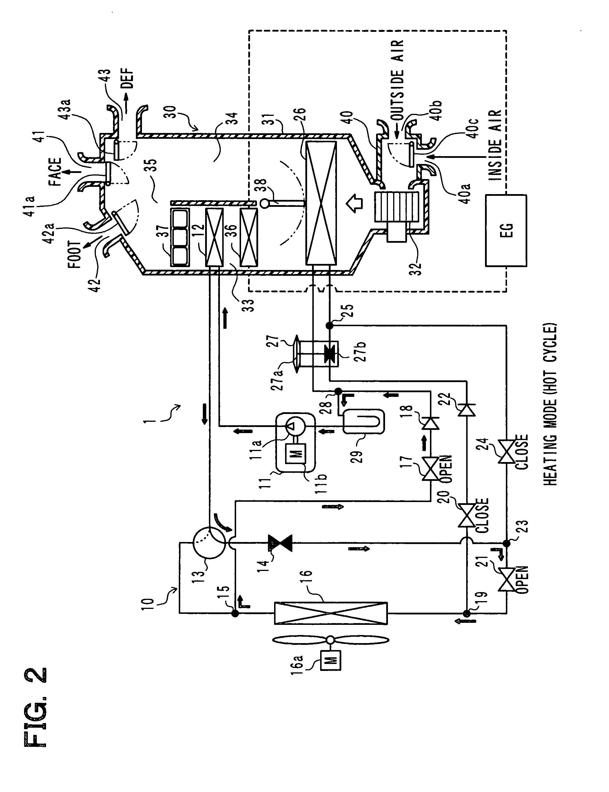
[0045]A first embodiment of the invention will be described below with reference to FIGS. 1 to 10. In the present embodiment, an air conditioner for a vehicle of the invention is applied to the so-called hybrid car which obtains a driving force for a vehicle traveling from an internal combustion engine (engine) EG and an electric motor for traveling. FIGS. 1 to 4 show an entire configuration diagram of an air conditioner 1 for a vehicle, according to the first embodiment and the following embodiments described later.

[0046]The air conditioner for a vehicle includes a vapor compression refrigeration cycle 10 which can switch among refrigerant circuits in a cooling mode (cooler cycle (i.e., COOL cycle)) for cooling the vehicle interior (i.e., vehicle compartment), in a heating mode (HOT cycle) for heating the vehicle interior, and in a first dehumidification mode (DRY_EVA cycle) and in a second dehumidification mode (DRY_ALL cycle) for dehumidifying the vehicle interior. FIGS. 1 to 4 i...

Example

[0238]A second embodiment of the present invention will be described with reference to FIGS. 1-8 and 11.

[0239]In the present embodiment, the number of revolutions of the compressor 11 determined in step S11 of step S6 will be described.

[0240]FIG. 11 is a flow chart showing a part of step S11 of FIG. 6, for determining the target evaporator blown-air temperature TEO that is a target temperature of air flowing out of the indoor evaporator 26 in the cooler cycle (cooling mode).

[0241]The number of revolutions of the compressor 11 in the cooler cycle is determined using the control map stored in the air conditioning controller 50 based on the target evaporator blown-air temperature TEO, as described in step S11.

[0242]In the present embodiment, the target evaporator blown-air temperature TEO of the indoor evaporator 26 is determined based on the control process shown in FIG. 11.

[0243]In step S60, a temporal target outlet air temperature f(Tam) is determined based on the outside air temper...

Example

[0267]A fourth embodiment of the present embodiment will be described with reference to FIGS. 1 to 8 and 13. FIG. 13 is a schematic diagram showing an arrangement state of an outdoor heat exchanger 16 of the refrigeration cycle 10, in a vehicle, according to the fourth embodiment of the invention. In FIG. 13, the up-and-down direction corresponds to a vertical direction.

[0268]In the present embodiment, the outdoor heat exchanger 16, adapted as a heat absorber in the heat pump cycle, is integrated with a radiator 46 and a blower fan 16a to form an integrated member, and the integrated member is arranged in an engine room of the vehicle. The outdoor heat exchanger 16 is disposed to be tilted with respect to the vertical direction so that a flow direction of air passing through the outdoor heat exchanger 16 is toward a lower side with respect to the horizontal direction, as shown in FIG. 13.

[0269]A core portion of the outdoor heat exchanger 16 includes a plurality of flat tubes 161, an...


PUM


Abstract

An air conditioner for a vehicle includes a vapor compression refrigeration cycle switchable between a heat pump cycle and a cooler cycle, a heat core configured to heat air to be blown into a vehicle compartment by using coolant of an engine of the vehicle as a heat source, and a controller configured to control operation of the vapor compression refrigeration cycle. The controller controls the vapor compression refrigeration cycle to be operated as the cooler cycle so as to perform a defrosting control of the outdoor heat exchanger, and outputs an operation request signal to the engine, when the controller determines that the outdoor heat exchanger is frosted.

Description

CROSS REFERENCE TO RELATED APPLICATION[0001]This application is based on Japanese Patent Application No: 2009-161455 filed on Jul. 8, 2009, the contents of which are incorporated herein by reference in its entirety.FIELD OF THE INVENTION[0002]The present invention relates to an air conditioner for a vehicle, which is provided with a vapor compression refrigeration cycle switchable between a heat pump cycle and a cooler cycle.BACKGROUND OF THE INVENTION[0003]Conventionally, in a vehicle air conditioner provided with a heat pump cycle, when an outdoor heat exchanger of the heat pump cycle is frosted, the heat pump cycle is switched to a cooler cycle, thereby defrosting the outdoor heat exchanger.[0004]JP-A-2002-174474 describes regarding a vehicle air conditioner that is provided with a heat pump cycle and a heater core. The heater core heats air to be blown into a vehicle compartment by using engine coolant as a heat source. In the vehicle air conditioner, in a case where an outdoor ...

Claims


Application Information

Patent Timeline
IPC IPC(8): F25D21/06F24H3/00F25D17/06
CPCB60H1/00785B60H1/00921B60H1/321B60H2001/3266F25D21/004F25B41/04F25B47/02F25B30/02F25B6/04B60H1/00885B60H2001/00961F25B41/20F25B41/24
Inventor OOMURA, MITSUYOHAYASHI, HIROYUKITAKEDA, YUKIHIKOICHISHI, YOSHINORI
Owner DENSO CORP
Why Eureka
Try Eureka