Gravimetric measuring instrument with releasable load receiver

a technology of gravity measurement and load receiver, which is applied in the direction of screws, threaded fasteners, instruments, etc., can solve the problems of inconvenient connection, insufficient weighing of weighing modules in industrial applications, and high contact pressure or bearing stress in the area of contact surfaces, etc., to achieve the effect of increasing the length of the part, reducing the number of windings, and reducing the number of screws

Active Publication Date: 2011-01-27
METTLER TOLEDO GMBH
View PDF15 Cites 7 Cited by
  • Summary
  • Abstract
  • Description
  • Claims
  • Application Information

AI Technical Summary

Benefits of technology

[0016]A further problem area in gravimetric measuring instruments concerns differences between the electrical potentials of different parts. For example, due to a build-up of electrostatic charges, it is possible for the load receiver to be attracted by the other parts of the gravimetric measuring instrument, which can likewise cause a considerable deviation of the measured value from the actual weight value of an object being weighed. In order to avoid a build-up of electrostatic charges on the load receiver, the weighing cell and the load receiver are preferably made of electrically conductive material, and an electrically conductive connection, for example a contact spring, is arranged between the weighing cell and the load receiver. This arrangement provides assurance that the housing of the gravimetric measuring instrument, the weighing cell arranged in the instrument, and the load receiver are at substantially

Problems solved by technology

However, due to this small taper angle, extremely large levels of contact pressure or bearing stress occur in the areas of the contact surfaces.
This type of connection is therefore only suitable for balances with small load capacities, even if the connection is made of metal.
Based on the foregoing issues, this type of connection is in most cases not suitable for weighing modules in industrial applications.
This connection method has the disadvantage that the installation and removal of the load receiver are very time-consuming, as the entire load receiver has to be turned in relation to the weigh

Method used


Image

  • Gravimetric measuring instrument with releasable load receiver
  • Gravimetric measuring instrument with releasable load receiver
  • Gravimetric measuring instrument with releasable load receiver

Examples


Embodiment Construction

)

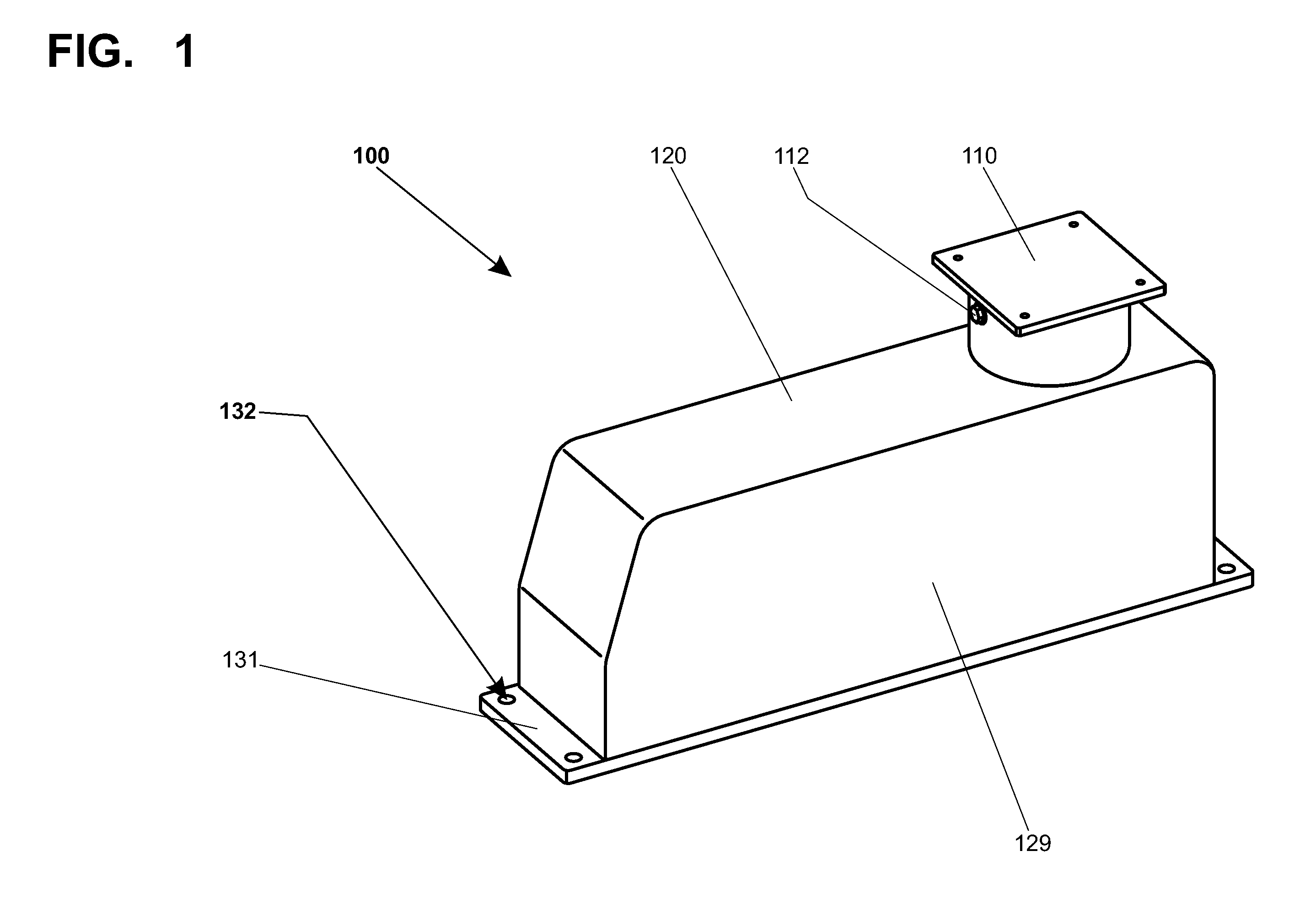
[0030]FIG. 1 is a three-dimensional representation of an exemplary gravimetric measuring instrument 100 in the form of a weighing module 120 with a load receiver 110 secured in place. The weighing module 120 includes a base plate 131 and a housing 129 that is releasably connected to the base plate 131. A weighing cell (not shown here) is arranged inside the housing 129. The base plate 131 has fastening locations 132, so that the weighing module 120 can be installed for example in a multi-track weighing system. The load receiver 110 is rigidly secured on a load-transmitting member (likewise not shown here) by means of an eccentric bolt 112.

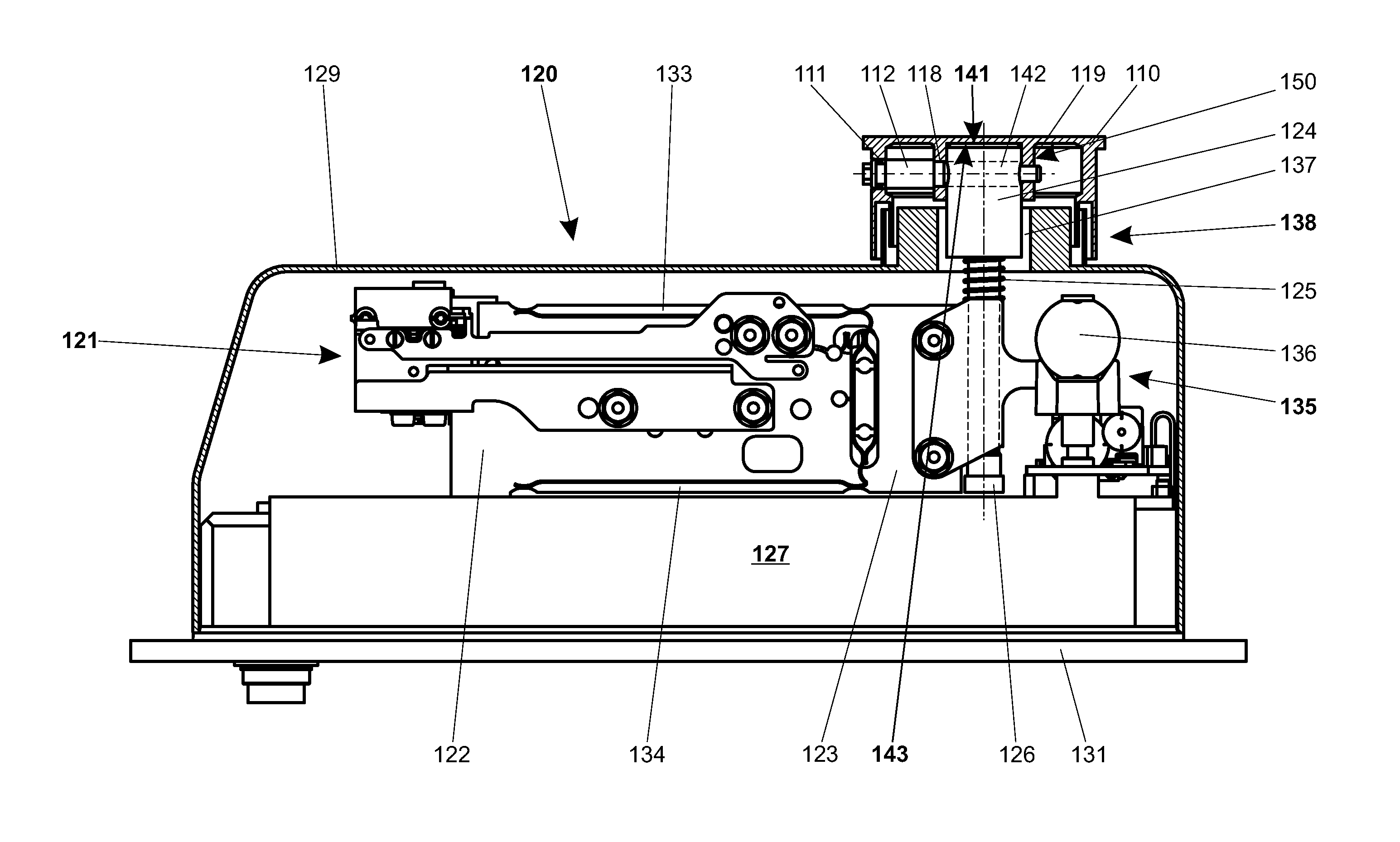
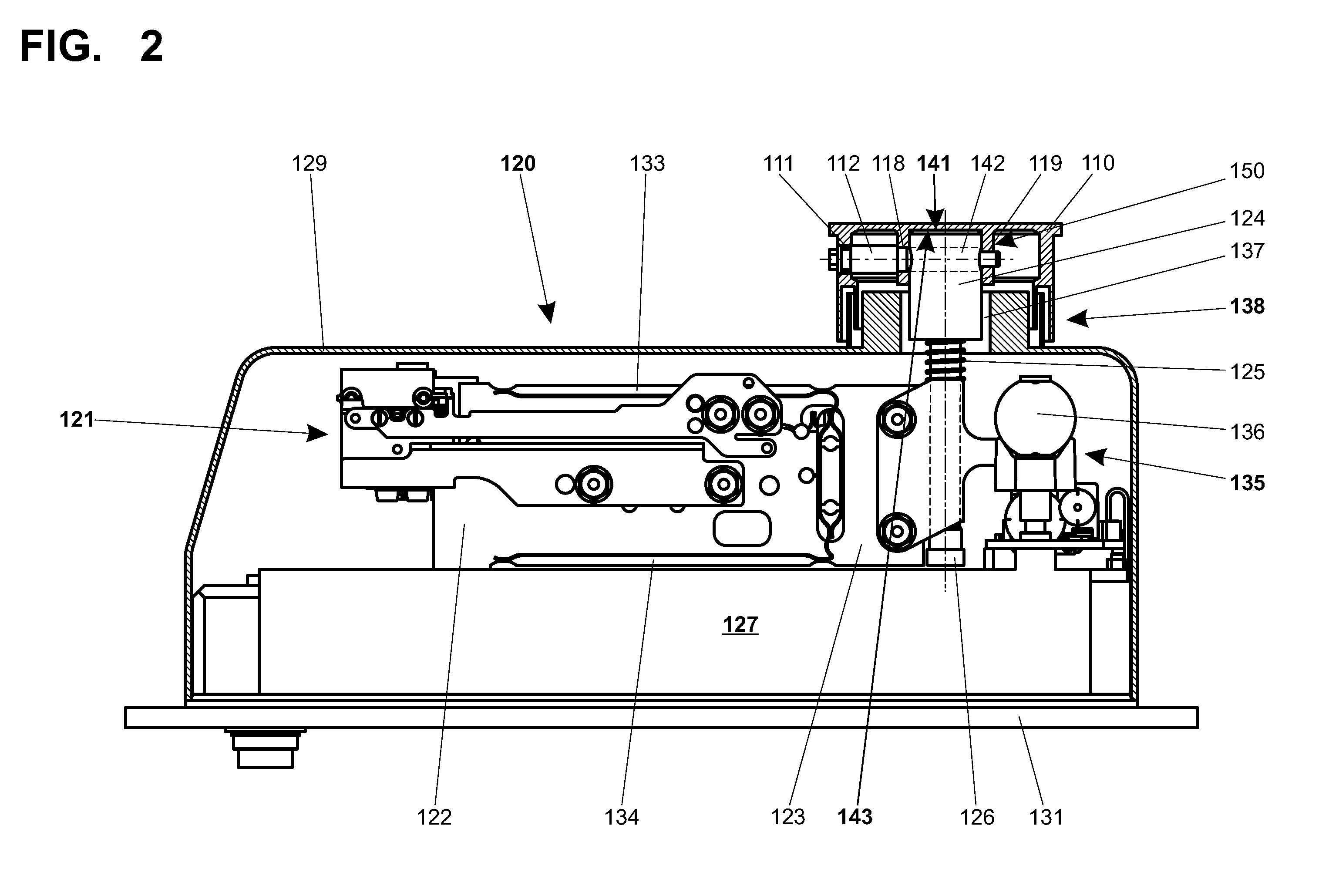
[0031]FIG. 2 depicts the weighing module 120 of FIG. 1 in a side view, wherein the housing 129 and the load receiver 110 are shown in cross-section. Arranged inside the housing 129 is a weighing cell 121 with a parallel-guiding mechanism. The parallel-guiding mechanism has a stationary parallel leg 122 and a movable parallel leg 123, wherein the m...


PUM


Abstract

A gravimetric measuring instrument that contains a weighing cell having a load-transmitting member. A load receiver can be coupled to the load-transmitting member through a releasable connection. A mechanical stop resides on the load-transmitting member, and a mechanical counter stop resides on the load receiver. By means of an eccentric bolt engaging the load receiver and the load-transmitting member, the mechanical stop can be pressed against the mechanical counter stop, whereby the stop can be clamped tight against the counter stop. With this arrangement, the load receiver can be rigidly but releasably secured to the load-transmitting member.

Description

CROSS-REFERENCE TO RELATED APPLICATIONS[0001]This application is entitled to, and claims, benefit of a right of priority under 35 USC §119 from European patent application 09166246.0, filed on 23 Jul. 2009, the content of which is incorporated by reference as if fully recited herein.TECHNICAL FIELD[0002]The present invention is directed to a gravimetric measuring instrument with a weighing cell that includes a load-transmitting member. A load receiver may be releasably connected to the load-transmitting member.BACKGROUND[0003]Gravimetric measuring instruments like those of interest here may serve, for example, as balances and weighing modules in many areas of industry, particularly in laboratories of research and development departments, but also as weighing modules in production departments, for example in quality control. Weighing modules, as used herein, are balances in which the display and / or the data entry unit is arranged separately from the weighing cell and the weighing cel...

Claims


Application Information

Patent Timeline
IPC IPC(8): G01G3/02
CPCG01G21/30G01G21/23
Inventor BIRRER, ADRIANMETZGER, ANDREASKOPPEL, THOMAS
Owner METTLER TOLEDO GMBH
Why Eureka
Try Eureka